Pneumatic rescue launch thrower

A gas cavity and gas transmission technology, applied in the direction of the casting line, etc., can solve the problems of gas leakage, unusability, increased cost, etc., to achieve the effect of accelerating the launching speed, increasing the throwing distance, and convenient operation.

Inactive Publication Date: 2019-01-18
缙云洛伊电子科技有限公司
View PDF0 Cites 0 Cited by
  • Summary
  • Abstract
  • Description
  • Claims
  • Application Information

AI Technical Summary

Problems solved by technology

[0002] The current pneumatic rescue launch thrower uses compressed air as a power to throw rescue objects (such as life buoys or lifelines, etc.) The speed of throwing makes it more difficult for long-distance rescue, and it cannot be used. Secondly, the chamber used to hold the compressed gas is not equipped with a sealing device, so the residual gas in the air chamber will leak into the external space and pass through. When the inflatable device inflates its air cavity, it will also cause gas leakage, resulting in increased cost, energy waste, and time-consuming rescue. Therefore, there is an urgent need for a safe and efficient pneumatic rescue launcher

Method used


Image

  • Pneumatic rescue launch thrower
  • Pneumatic rescue launch thrower
  • Pneumatic rescue launch thrower

Examples


Embodiment Construction

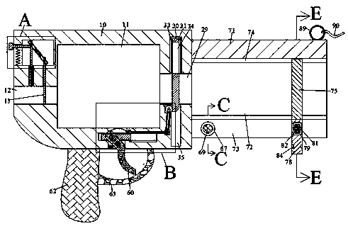
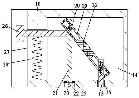
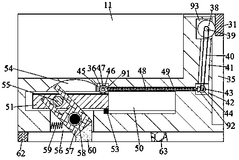
[0015] Combine below Figure 1-6 The present invention is described in detail, and for convenience of description, the orientations mentioned below are now stipulated as follows: figure 1 The up, down, left, right, front and back directions of the projection relationship itself are the same.

[0016] refer to Figure 1-6 , according to an embodiment of the present invention, a pneumatic rescue launching thrower includes a gun body 10, an air cavity 11 is provided inside the gun body 10, and an air inlet slot is provided on the left side of the air cavity 11 to communicate with the external space 12. The air intake groove 12 is provided with a sealing block 13 whose upper end is rotatably connected with the sealing device, and the right side of the air cavity 11 is connected with the external space to be provided with an air delivery groove 29, and the upper side of the air delivery groove 29 is communicated with a set There is a first chute 30 with the opening facing downwar...


PUM


Abstract

The invention discloses a pneumatic rescue launch thrower, which includes a gun body, the gun body is provided with an air cavity, A left side of that air chamber is communicated with an external space and provided with an air inlet groove, the air inlet groove is provided with a sealing block whose upper end is rotatably connected with the sealing device, A right side of that air chamber is communicated with an external space and provided with an air conveying groove, An upper side of that air convey groove is communicated with a first slide groove with an opening facing downward, the advantage of that invention are simple structure, easy to operate, A rescue object is clamped to the thrower by a clamping device, subsequently inflating the air chamber, the sealing device ensures the tightness of the air cavity, which allows the device to move after inflation to adjust the firing angle without leakage of gas in the air chamber and facilitates operation, At that same time, the descend and unlocking clam device of the sealing plate accelerates the firing speed of the rescue object through the elastic rope, increase the throwing distance, and can be used in a large range. The sealingplate is connected with the air conveying groove through the transmission device to provide driving force for the rescue object launch.

Description

technical field [0001] The invention relates to the technical field of rescue devices, in particular to a pneumatic rescue launching thrower. Background technique [0002] The current pneumatic rescue launch thrower uses compressed air as a power to throw rescue objects (such as life buoys or lifelines, etc.) The speed of throwing makes it more difficult for long-distance rescue, and it cannot be used. Secondly, the chamber used to hold the compressed gas is not equipped with a sealing device, so the residual gas in the air chamber will leak into the external space and pass through. When the inflatable device inflates its air cavity, it will also cause gas leakage, resulting in increased cost, energy waste, and time-consuming rescue. Therefore, there is an urgent need for a safe and efficient pneumatic rescue launcher. Contents of the invention [0003] The object of the present invention is to provide a pneumatic rescue launching thrower for overcoming the above-mentione...

Claims


Application Information

Patent Timeline
Patent Type & Authority Applications(China)
IPC IPC(8): B63C9/26
CPCB63C9/26
Inventor 胡梦洁
Owner 缙云洛伊电子科技有限公司
Why Eureka
Try Eureka