UAV hatch cover quick lock device
A technology of lock device and canopy, which is applied in the direction of fuselage, aircraft accessories, aircraft parts, etc., can solve the problems that operability performance hinders the scope and prospect of UAV application, inconvenient disassembly and assembly, and affects the rapidity of the system, etc.
- Summary
- Abstract
- Description
- Claims
- Application Information
AI Technical Summary
Problems solved by technology
Method used
Image
Examples
Embodiment 1
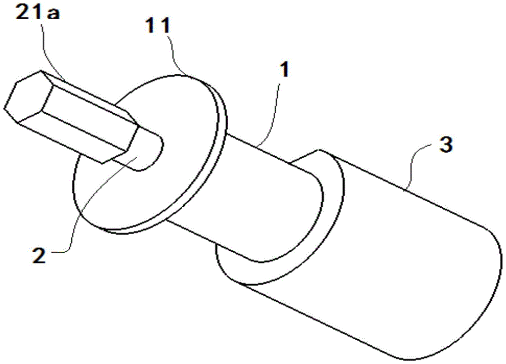
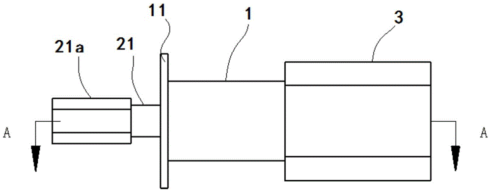
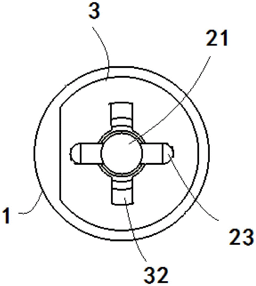
[0030] see Figure 1-4 , the present invention provides a kind of unmanned aerial vehicle canopy fast locking device, comprising:
[0031] The hatch cover mounting seat 1 is installed on the hatch cover and is cylindrical; one end is open, the other end has an end cover 11, and the center of the end cover 11 has a hole for the pin shaft 21 to pass through. Between the end cover 11 and the pin shaft 21 For tight fit, it can prevent dust and short-term rainproof function;
[0032] The lock cylinder 2 includes a pin shaft 21 pierced in the hatch mounting seat 1, a spring 22 pierced on the pin shaft 21 and a lock pin 23 detachably mounted on the pin shaft 21, and the pin shaft 21 has a spring seat 24. The spring 22 is installed between the spring seat 24 and the lock pin 23; one end of the pin shaft 21 has a rotating head 21a for easy rotation, and the rotating head 21a extends outward from the hatch cover mounting seat 1, and the rotating head 21a is in the shape of a positive p...
Embodiment 2
[0039] see Figure 5-10 , on the basis of Embodiment 1, a limit groove 33 for limiting the rotation angle of the lock pin 23 is also provided on the end extending along the lock groove 32 on the fuselage mounting seat 3, and the cross section of the limit groove 33 includes a pin shaft 21 is fitted with a central hole 33a and two sectors 33b symmetrically distributed with respect to the center of the central hole, and the diameter of the sectors 33b is the same as the length of the lock pin 23 . The central angle of the sector 33b is between 60° and 120°, preferably 90°. A groove 3c for limiting the rotation of the lock pin 23 is provided on the end surface 3b extending along the lock groove on the body mount 3 , and the angle between the groove 3c and the lock groove 32 is 90 degrees.
[0040]Press down the pin shaft 21 and rotate it 90° clockwise, the quick lock is locked, and the pin shaft 21 is turned 90° counterclockwise to pop up, and the quick lock is opened.
[0041]...
PUM
 Abstract
Description
Claims
Application Information
 - R&D
- Intellectual Property
- Life Sciences
- Materials
- Tech Scout
- Unparalleled Data Quality
- Higher Quality Content
- 60% Fewer Hallucinations
Browse by: Latest US Patents, China's latest patents, Technical Efficacy Thesaurus, Application Domain, Technology Topic, Popular Technical Reports.
© 2025 PatSnap. All rights reserved.Legal|Privacy policy|Modern Slavery Act Transparency Statement|Sitemap|About US| Contact US: help@patsnap.com


