
Locking connector

A connector and connection state technology, which is applied in the direction of connection, two-part connection device, and parts of the connection device, etc., can solve the problems of wear of the lock and difficulty in unlocking.

Pending Publication Date: 2022-07-19
江苏瀚达电力科技有限公司
View PDF0 Cites 0 Cited by
  • Summary
  • Abstract
  • Description
  • Claims
  • Application Information

AI Technical Summary

Problems solved by technology

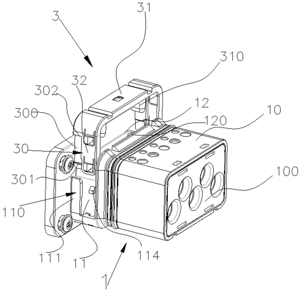
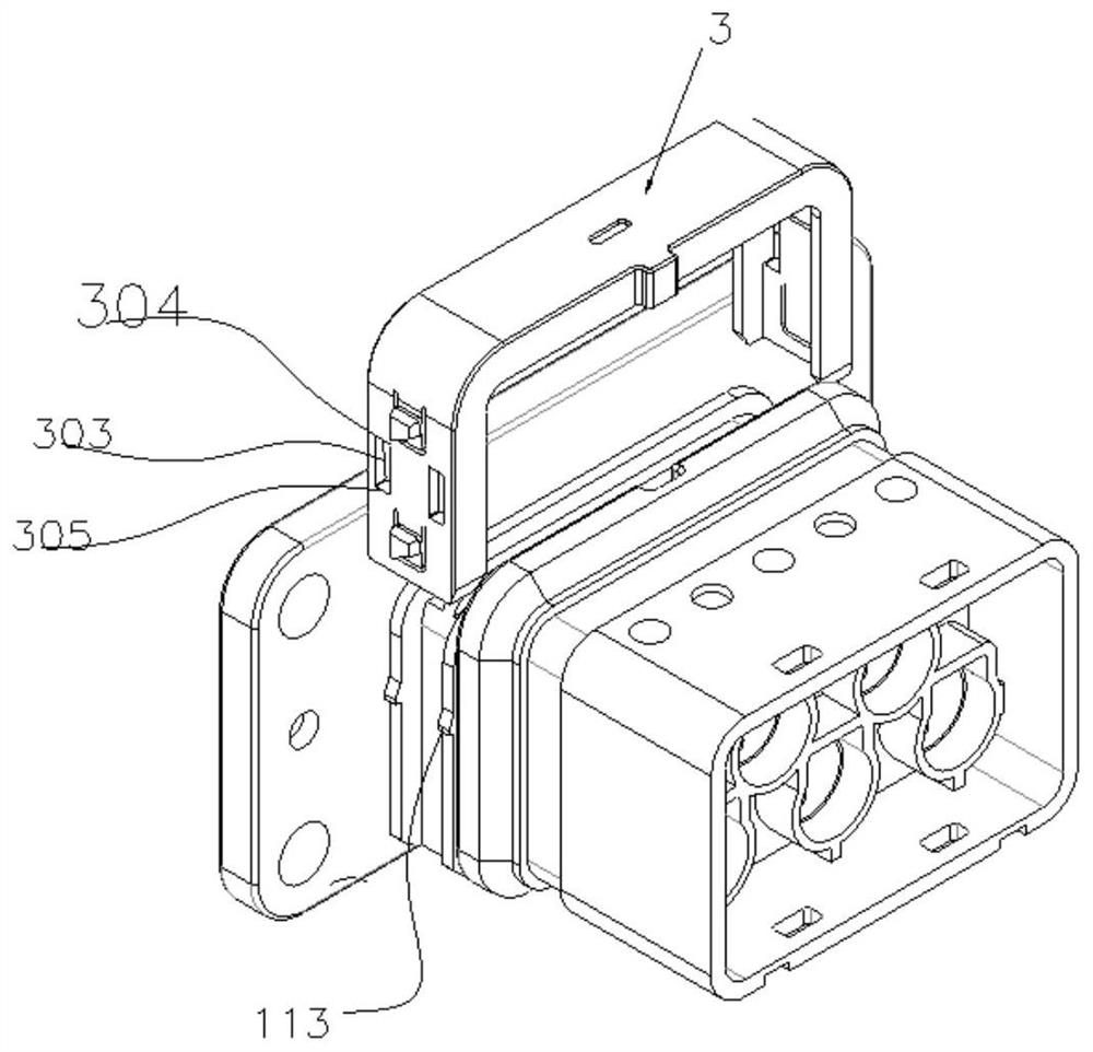
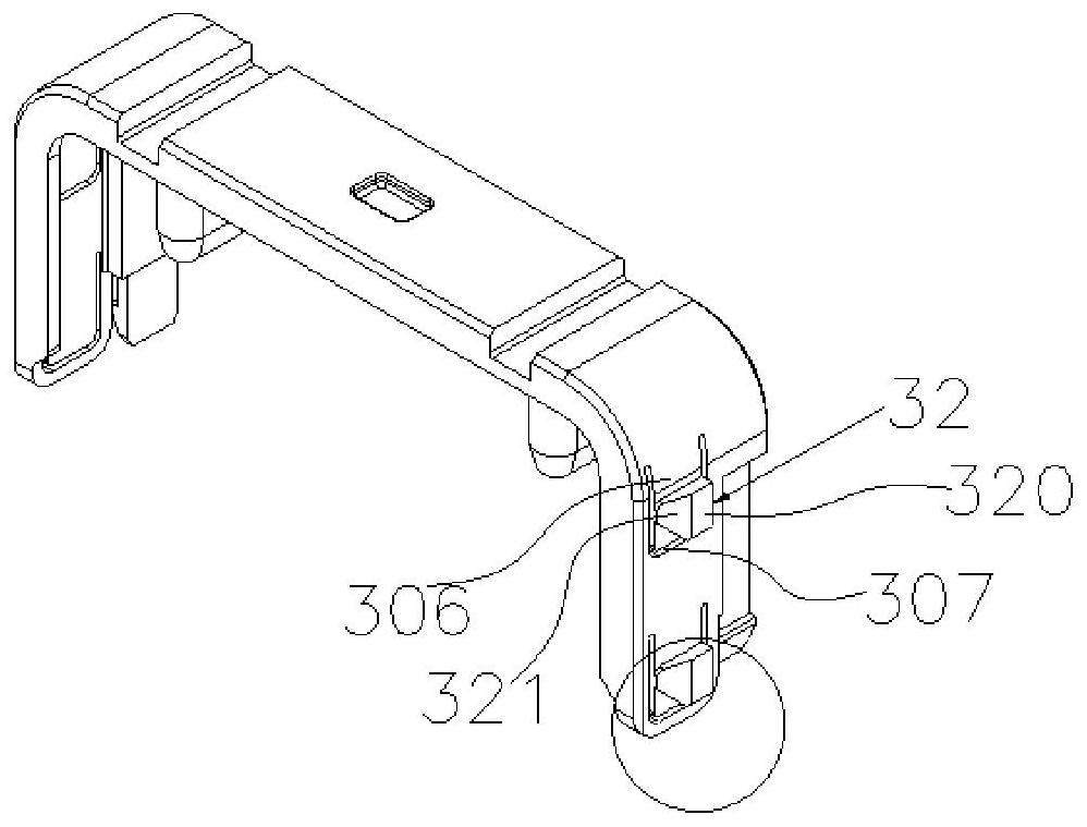
[0003] The present invention provides a locking connector, which solves the problems of difficulty in unlocking and wear of locking parts caused by exposed structural parts in the prior art

Method used


Image

  • Locking connector
  • Locking connector
  • Locking connector

Examples


Embodiment Construction

[0053] The features and exemplary embodiments of various aspects of the present invention will be described in detail below. In order to make the objectives, technical solutions and advantages of the present application more clear, the present application will be further described in detail below with reference to the accompanying drawings and specific embodiments. It should be understood that the specific embodiments described herein are only configured to explain the present application, and are not configured to limit the present application. It will be apparent to those skilled in the art that the present application may be practiced without some of these specific details. The following description of the embodiments is merely intended to provide a better understanding of the present invention by illustrating examples of the present application.

[0054] It should be noted that, in this document, relational terms such as first and second are only used to distinguish one en...


PUM


Abstract

The locking connector comprises a first connector and a second connector matched with the first connector, the first connector comprises a body part and a lock catch piece arranged on the body part, and the connection state of the lock catch piece and the body part comprises a first connection state and a second connection state; when the initial connection state of the locking fastener and the body part is a first connection state, the second connector is fixed with the first connector through the locking fastener, and when the connection state of the locking fastener and the body part is converted from the first connection state to a second connection state, the second connector is separated from the locking fastener; and if the initial connection state of the locking fastener and the body part is a second connection state, the second connector is matched with the locking fastener, so that the connection state of the locking fastener and the body part is reset to the first connection state, and the fixation and separation of the second connector and the first connector can be realized.

Description

technical field [0001] The invention relates to the technical field of electrical transmission equipment, in particular to a locking connector used in the transmission process of electrical lines. Background technique [0002] The locking connector in the prior art has the problems that it is difficult to unlock after the locking member is locked, and the locking member is exposed to the surface of the connector, causing damage to the locking member, and the structure is cumbersome. SUMMARY OF THE INVENTION [0003] The present invention provides a locking connector, which solves the problems in the prior art that the unlocking is difficult and the locking parts are worn out due to the exposed structural parts. [0004] An embodiment of the present invention provides a locking connector, which includes: a first connector and a second connector matched with the first connector, the first connector includes a body part and is disposed on the body part The locking piece on t...

Claims


Application Information

Patent Timeline
IPC IPC(8): H01R13/629H01R13/639H01R24/00
CPCH01R24/00H01R13/629H01R13/639
Inventor 窦丹风钱志华
Owner 江苏瀚达电力科技有限公司
Learn More