
Power System for Locomotive Lighting

A technology for lighting devices and power systems, used in signaling devices, vehicle components, transportation and packaging, etc.

Active Publication Date: 2018-02-16
南京坦索光电有限公司
View PDF8 Cites 0 Cited by
  • Summary
  • Abstract
  • Description
  • Claims
  • Application Information

AI Technical Summary

Problems solved by technology

Existing locomotive lighting equipment often includes high beams, low beams and signal lights. The control method of the traditional lighting device is to drive the high beams, low beams and signal lights to work alternately through the corresponding power supply device. However, for complex road conditions The locomotives running under, such as mining area vehicles, etc., have much higher requirements for the signal indication of signal lamps than ordinary vehicles, and they must also be illuminated to a certain extent while signaling, so the above-mentioned high beam, low beam and The staggered working method of signal lights is difficult to meet its needs

Method used


Image

  • Power System for Locomotive Lighting
  • Power System for Locomotive Lighting
  • Power System for Locomotive Lighting

Examples


Embodiment 1

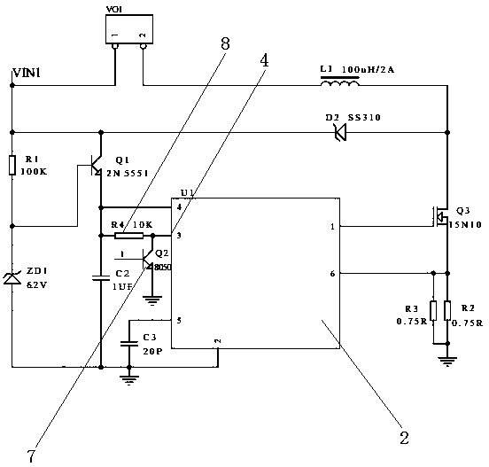
[0021] Such as Figure 1 to 4 A power supply system suitable for locomotive lighting devices is shown, which includes a high beam circuit, a low beam circuit, a signal light circuit, and a control circuit; the high beam circuit, the low beam circuit, and the signal light circuit respectively include There are a high beam control chip 1, a low beam control chip 2, a signal light control chip 3. The high beam control chip 1, a low beam control chip 2, and a signal light control chip 3 are respectively provided with an external control enable port 4; The power supply system suitable for locomotive lighting devices includes a control circuit, the control circuit is provided with a first control chip 5 and a second control chip 6, the first control chip 5 is connected with the signal light control chip 3, the second control The chip 6 is respectively connected to the external control enable port 4 of the high beam control chip 1 and the low beam control chip 2.

[0022] As an improvem...

Embodiment 2

[0029] As an improvement of the present invention, the high beam control chip 1, the low beam control chip 2, and the signal light control chip 3 all adopt QX9920 chips. The above-mentioned QX9920 chip adopts a fixed off-time peak current control method, and its operating frequency can reach up to 1MHz, which can reduce the volume of external inductors and filter capacitors, improve efficiency, and save PCB area.

[0030] The remaining features and advantages of this embodiment are the same as those of the first embodiment.

Embodiment 3

[0032] As an improvement of the present invention, the first control chip 5 and the second control chip 6 both adopt NE555 chips. The NE555 chip mentioned above can provide good working stability and improve the overall cost of the power supply system.

[0033] Figure 1 to 4 in, figure 1 versus figure 2 The high beam circuit in the low beam circuit and the switching transistor 7 in the low beam circuit are connected to Figure 4 The output terminal (VO) of the first control chip 5 in the image 3 The input terminal (pin 3) of the signal light control chip 3 in the signal light circuit in the signal light circuit is connected to Figure 4 The output terminal (VO) of the second control chip 6, Figure 1 to 4 The power supply system suitable for the lighting device of the locomotive in the present invention is connected according to the above connection method.

[0034] Further analysis, such as Figure 1 to 3 As shown, in the high beam circuit, the low beam circuit and the signal l...


PUM


Abstract

The invention discloses a power supply system suitable for a lighting device of a locomotive. The power supply system comprises a high-beam lamp control chip, a low-beam lamp control chip and a signal lamp control chip, which are respectively provided with one or more external control enabled sockets. The power supply system comprises a control circuit, wherein a first control chip and a second control chip are arranged in the control circuit, the first control chip is connected with the signal lamp control chip, and the second control chip is connected with the high-beam lamp control chip and the low-beam lamp control chip respectively. Compared with conventional locomotive lighting, the power supply system suitable for the lighting device of the locomotive, adopting the technical scheme disclosed by the invention, has the advantages that brightness control in the alternative work process of high / low-beam lamps and signal lamps of the locomotive can be realized, so that in the travelling process of the lighting device of the locomotive based on the power supply system, the marking effects of signals and the work stability of the lighting device both are improved.

Description

Technical field [0001] The invention relates to a power electronic system, in particular to a power supply system suitable for locomotive lighting devices. Background technique [0002] The lighting equipment of the locomotive is one of the necessary devices during the driving process of the locomotive, which can effectively ensure the safety of the locomotive itself and other vehicles and pedestrians on the traveling distance of the locomotive. Existing locomotive lighting equipment often includes high beams, low beams and signal lights. The traditional lighting device control method is to drive the high beams, low beams and signal lights to work alternately through the corresponding power supply device. However, for complex road conditions Locomotives traveling underneath, such as mining vehicles, have much higher requirements for signal indications of signal lights than ordinary vehicles, and they must also be illuminated to a certain degree while signalling, which leads to th...

Claims


Application Information

Patent Timeline
Patent Type & Authority Patents(China)
IPC IPC(8): B60Q1/04B60Q1/00B60Q1/14
CPCB60Q1/00B60Q1/04B60Q1/1407B60Q1/1415
Inventor 杨厚云
Owner 南京坦索光电有限公司
Learn More