
Automatic Control Method of Second Surfacing Welding after Large Roller Shaft Wears

A roll shaft and welding point technology, applied in the field of automatic control system for surfacing worn roll shafts, can solve the problems of uneven hardness of rolls, failure to achieve original performance, poor handling, etc., and achieve appropriate control of welding current and welding voltage. , The chemical composition and performance are uniform, and the welding speed is selected properly.

Active Publication Date: 2017-11-28
SHENZHEN RILAND IND
View PDF7 Cites 0 Cited by
  • Summary
  • Abstract
  • Description
  • Claims
  • Application Information

AI Technical Summary

Problems solved by technology

[0002] During the use of large-scale roll shafts, due to large local strength changes, the rolls will be damaged, such as wear, collapse, cracks on the surface of the roll, breakage of the roll, uneven hardness of the roll, etc., which will lead to the scrapping of the roll, especially in cold rolling mills. This phenomenon often occurs in continuous casting steel plants
Because the rollers are made of special steel, and the special steel is manufactured through forging and complex heat treatment process, the price is relatively high, and the annual loss of the rollers in the steel mill is huge, and then it cannot be repaired or cannot be repaired. It was scrapped because of its original performance, which caused great economic losses to my country's metallurgical industry.
[0003] Most of the existing welding is manually operated, which is prone to control errors leading to poor handling, and through manual judgment and control of the surfacing welding of the worn roller shaft, the technical requirements for the operator are high, the efficiency is low, and the accuracy is not high

Method used


Image

  • Automatic Control Method of Second Surfacing Welding after Large Roller Shaft Wears

Examples


Embodiment Construction

[0040] All the features disclosed in this specification, or all disclosed methods or steps in the process, except for mutually exclusive features and / or steps, can be combined in any manner.

[0041] Any feature disclosed in this specification (including any additional claims and abstract), unless specifically stated, can be replaced by other equivalent or alternative features with similar purposes. That is, unless otherwise stated, each feature is just one example of a series of equivalent or similar features.

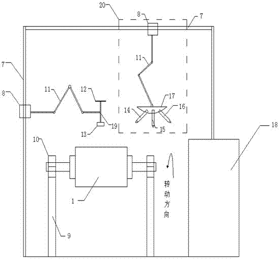
[0042] Such as figure 1 As shown, an automatic control method of an automatic control system for surfacing worn roll shafts includes:

[0043] Step 1: Input the start point and end point of the first welding point on the roller shaft respectively in the input module, and convert them into the first start point digital signal 0011 and the first end point digital signal 0012 and transmit them to the PLC; input the second welding point The start and end points on the roller ...


PUM


Abstract

The invention discloses an automatic double-overlaying control system and method for an abraded of a large roller shaft. A starting point and a terminal point of a welding point on the roller shaft are input into an input module and converted into digital signals which are transmitted to a programmable logic controller (PLC), a corresponding result is obtained through calculation by means of the PLC, and an executing signal is transmitted to a sliding module, an extending and retracting module, a polishing module, a gear module, an overlaying module, a flaw detection module and a heating module. By means of the control system and method, automatic overlaying of the abraded roller shaft is achieved, polishing, cleaning, welding, flaw detection and heating can be conducted on the abraded roller shaft automatically, and manpower resources are greatly saved; in addition, the accuracy and efficiency are high.

Description

Technical field [0001] The invention relates to the field of surfacing welding, in particular to an automatic control system and method for surfacing worn roller shafts. Background technique [0002] During the use of large rollers, due to the large changes in local strength, the rollers will wear out, chipped, cracks on the surface of the rollers, roller fractures, uneven hardness of the rollers and other damages, which will lead to scrapped rollers, especially in cold-rolled steel mills. Such phenomena often occur in continuous casting steel plants. Because the rollers are all made of special steel, and the special steel is manufactured through forging and complicated heat treatment process, the price is relatively high, the roller loss in the steel plant is huge every year, and then it cannot be repaired or cannot be reached after repairing. The original performance is scrapped, which causes significant economic losses to my country's metallurgical industry. [0003] The existi...

Claims


Application Information

Patent Timeline
Patent Type & Authority Patents(China)
IPC IPC(8): B23K9/04B23K9/18B23K9/235B23K9/095
CPCB23K9/048B23K9/095B23K9/0956B23K9/18B23K9/235
Inventor 钱诗浩崔华徐月玲
Owner SHENZHEN RILAND IND
Learn More