cnc cooperative control device and numerical control system

A technology of collaborative control and speed control, applied in the field of numerical control, can solve problems such as control errors

Active Publication Date: 2017-06-20
HUNAN TIANGUAN ELECTRONICS INFORMATION TECH
View PDF5 Cites 0 Cited by
  • Summary
  • Abstract
  • Description
  • Claims
  • Application Information

AI Technical Summary

Problems solved by technology

[0004] Based on this, it is necessary to provide a CNC cooperative control device and numerical control system that is not prone to control errors in view of the problem that existing CNC cooperative control devices are prone to control errors.

Method used


Image

  • cnc cooperative control device and numerical control system
  • cnc cooperative control device and numerical control system

Examples


Embodiment Construction

[0013] In order to make the object, technical solution and advantages of the present invention clearer, the present invention will be further described in detail below according to the drawings and embodiments. It should be understood that the specific implementations described here are only used to explain the present invention, not to limit the present invention.

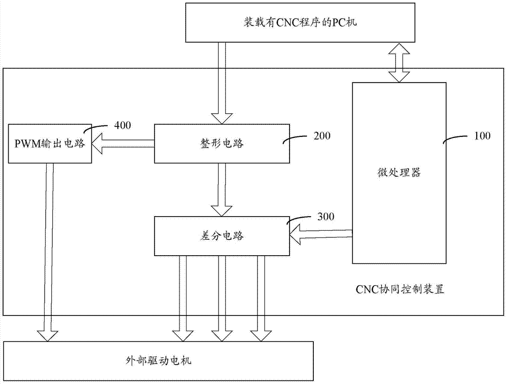
[0014] Such as figure 1 As shown, a CNC cooperative control device includes a microprocessor 100, a shaping circuit 200, a differential circuit 300 and a PWM output circuit 400;

[0015] The input end of the shaping circuit 200 is externally connected to a PC, the first output end of the shaping circuit 200 is connected to the input end of the differential circuit 300, and the second output end of the shaping circuit 200 is connected to the PWM output circuit 400 The input end of the differential circuit 300 and the output end of the PWM output circuit 400 are respectively connected to the external drive motor, t...


PUM


Abstract

The invention provides a CNC cooperative control device and a numerical control system. The CNC cooperative control device comprises a microprocessor, a shaping circuit, a differential circuit and a PWM output circuit, wherein the shaping circuit performs shaping processing on signals output by an external PC computer so as to generate a jitter-free and clear main signal and a spindle motor rotating speed control signal; the differential circuit differentiates the jitter-free and clear main signal into a multipath signal; when an enable signal is received, the multipath signal is output to an external driving motor, the PWM output circuit generates analog voltage to be output to the external driving motor according to the spindle motor rotating speed control signal; the microprocessor monitors the minimum time interval of an MODBUS data packet output by the PC; and when the minimum time interval of the MODBUS data packet output by the PC exceeds a preset threshold value, the enable signal is stopped outputting to the differential circuit, so that the differential circuit stops outputting the multipath signal to the external driving motor.

Description

technical field [0001] The invention relates to the technical field of numerical control, in particular to a CNC cooperative control device and a numerical control system. Background technique [0002] CNC (Computer numerical control, computer numerical control machine tool) is an automatic machine tool controlled by a program. The control system can logically process the program specified by the control code or other symbolic instructions, and decode it through the computer, so that the machine tool can perform the specified action, and the blank can be processed into a semi-finished product part through tool cutting. [0003] In actual production and life, when the CNC system is not running, the output state of the parallel port is uncertain, and the PC is running unstable, and the CNC system often crashes, and the pulse output by the parallel port does not meet the requirements, resulting in control errors. Contents of the invention [0004] Based on this, it is necess...

Claims


Application Information

Patent Timeline
Patent Type & Authority Patents(China)
IPC IPC(8): G05B19/414
CPCG05B19/4145G05B2219/33001
Inventor 胡志坤罗山刘绍辉陈红钊刘俊杰唐品利
Owner HUNAN TIANGUAN ELECTRONICS INFORMATION TECH
Why Eureka
Try Eureka