Liquid cooling system for server

A server and blade server technology, applied in the direction of using liquid cooling for modification, cooling/ventilation/heating transformation, etc., can solve the problems of inability to fill and empty, difficult to fill or empty, complicated and cumbersome process, etc., and achieve convenient operation Effect

Active Publication Date: 2016-03-23
DAWNING INFORMATION IND BEIJING +1
View PDF3 Cites 5 Cited by
  • Summary
  • Abstract
  • Description
  • Claims
  • Application Information

AI Technical Summary

Problems solved by technology

[0005] The liquid cooling system for servers of the present invention solves the problem that in actual operation, the process is very complicated and cumbersome, it is not easy to fill or empty, and it is impossible to independently fill and drain a certain blade server without affecting other blade servers. emptying problem

Method used


Image

  • Liquid cooling system for server

Examples


Embodiment Construction

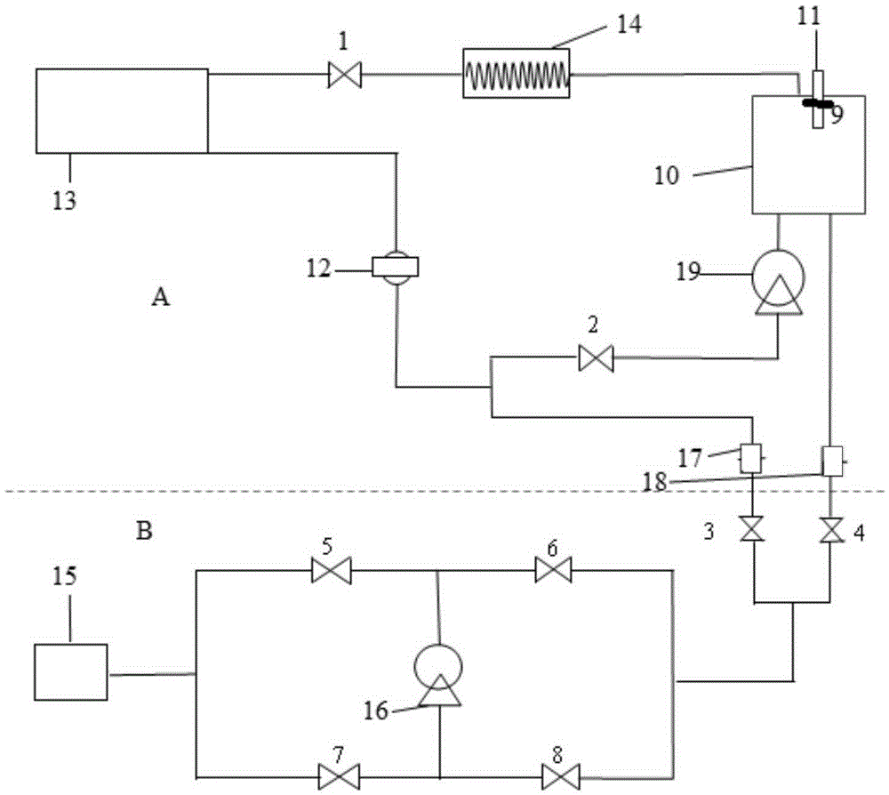
[0022] figure 1 It is a schematic structural diagram of an embodiment of the liquid cooling system for servers of the present invention. Such as figure 1 As shown, the liquid cooling system for servers in this embodiment may include: a refrigeration device A and a liquid-filling and liquid-receiving device B, wherein the liquid-filling and liquid-receiving device B is detachably connected to the refrigeration device A to supply cooling equipment to the refrigeration device A. The refrigerant is drawn in or discharged from the refrigeration unit A.

[0023] Specifically, the upper part is a schematic diagram of the structure of the cooling device A. When the server is running, the heat generated by the CPU and various electronic components causes the refrigerant to boil and become refrigerant vapor. The refrigerant vapor and hot fluid generated by each server flow out through the top of the server, gather together, and become cold fluid again after condensation, and the cold ...


PUM


Abstract

The invention relates to a liquid cooling system for a server. As a liquid filling and liquid recovering device is detachably connected with a refrigeration device, a refrigerant is pumped in the refrigeration device or the refrigerant is exhausted from the refrigeration device. The operation is convenient, liquid filling and draining on a liquid storage tank and a blade can be realized, and liquid filling and draining can be realized for a certain blade in a condition of realizing no to influence normal refrigeration of other blade servers.

Description

technical field [0001] The invention relates to the technical field of computer cooling, in particular to a liquid cooling system for servers. Background technique [0002] Most of the computers currently in use rely on cold air to cool down the machine, but in data centers, air cooling alone is not enough to meet the heat dissipation requirements of high heat flux density servers. Water cooling or liquid cooling has two major advantages: first, it directs the coolant directly to the heat source, rather than indirect cooling like air cooling; second, compared with air cooling, the heat transfer efficiency per unit volume is as high as 3500 times. Water-cooled radiators appeared in the market around 2008. Server giants such as HP and IBM and other companies focusing on data center technology have successively launched water-cooled heat dissipation products. Whether in a direct liquid cooling system or an indirect liquid cooling system, the use of a liquid storage tank is ess...

Claims


Application Information

Patent Timeline
Patent Type & Authority Applications(China)
IPC IPC(8): H05K7/20
CPCH05K7/2029
Inventor 王晨
Owner DAWNING INFORMATION IND BEIJING
Why Eureka
Try Eureka