Single-phase ground line selection method with function of accuracy improvement for small-current grounding system
A low-current grounding and single-phase grounding technology, applied in the direction of the fault location, can solve problems such as unobvious fault characteristics, complex and changeable fault conditions in the small-current grounding system, and difficult line selection with high accuracy, so as to achieve small impact, The effect of strong resistance to excessive resistance and high line selection accuracy
- Summary
- Abstract
- Description
- Claims
- Application Information
AI Technical Summary
Problems solved by technology
Method used
Image
Examples
example 1
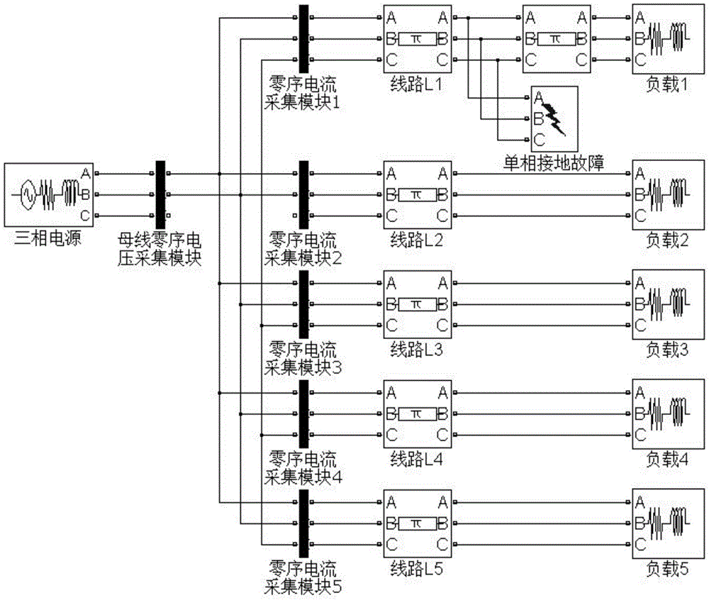
[0024] Ungrounded neutral system with figure 1 Take the structure diagram shown as an example, the model in the figure contains 5 outgoing lines L 1 ~ L 5 , where L 1 , L 2 For overhead lines, the lengths are 20km and 6km respectively; L 3 , L 4 is the cable, the lengths are 10km and 3km respectively; L 5It is a mixed line of overhead cables, the cable part is close to the busbar, the length is 5km, and the length of the overhead line is 7km. The parameters of overhead lines and cable lines are shown in Tables 1 and 2. All loads adopt "Three-phaseSeriesRLCLoad", the neutral point is not grounded, and the power factor is 0.8.
[0025] Table 1 Overhead Line Parameters
[0026] phase sequence
Resistance (Ω / km)
Capacitance (μF / km)
Inductance (mH / km)
Positive sequence
0.17
0.061
7.600
zero sequence
0.23
0.038
34.400
[0027] Table 2 Cable Line Parameters
[0028] phase sequence
Resistance (Ω / km...
example 2
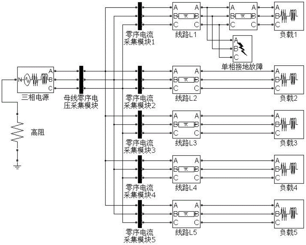
[0041] The neutral point is connected to the high-impedance grounding system with image 3 The structure diagram shown is an example. The number of outgoing lines, line parameters, and loads of the system are the same as those of the neutral point ungrounded system. The neutral point grounding resistance generally follows the neutral point current I R =1~1.5I C to choose, I C It is the capacitive current to the ground of the system. According to the simulation model and line parameters, the neutral point resistance is 200Ω.
[0042] The fault location is selected at the 2km distance from the busbar of the third outgoing line, the A phase is grounded through a 5000 ohm resistor, and the fault phase angle is 0°. The line selection results are shown in Table 5.
[0043] Table 5 Fault line selection results of the neutral point through the high-impedance grounding system (L 3 / 5000€ / 0°)
[0044]
[0045] It can be seen from Table 5 that due to the large grounding resistanc...
example 3
[0047] The neutral point is grounded by the arc suppression coil Figure 5 Take the structure diagram shown as an example, the number of outgoing lines, line parameters, and loads of the system are the same as those of the neutral point ungrounded system, the compensation degree of the arc suppression coil is 5%, and the distributed capacitance C of the system to ground is obtained from the line parameters Σ , and then calculate the arc suppression coil equivalent inductance L=1 / 1.05*1 / (3ω 2 C Σ ) = 0.6554H. The active loss of the arc suppression coil is 3% of the inductive loss, R L =0.03ωL=6.1767Ω.
[0048] The fault location is selected at the 2km distance from the busbar of the 3rd outgoing line, the A phase is grounded through a 50 ohm resistor, and the fault phase angle is 45°. The line selection results are shown in Table 6.
[0049] Table 6 Results of fault line selection of neutral point via high-impedance grounding system (L 3 / 50Ω / 45°)
[0050]
[0051] No...
PUM
 Abstract
Description
Claims
Application Information
 - R&D
- Intellectual Property
- Life Sciences
- Materials
- Tech Scout
- Unparalleled Data Quality
- Higher Quality Content
- 60% Fewer Hallucinations
Browse by: Latest US Patents, China's latest patents, Technical Efficacy Thesaurus, Application Domain, Technology Topic, Popular Technical Reports.
© 2025 PatSnap. All rights reserved.Legal|Privacy policy|Modern Slavery Act Transparency Statement|Sitemap|About US| Contact US: help@patsnap.com


