
Shell-and-tube apparatus for heat recovery from hot process stream

一种壳管式、工艺流的技术,应用在利用热载体的蒸汽发生方法、蒸汽分离装置、照明和加热设备等方向,能够解决没有提供完全令人满意解决方案等问题,达到相关风险减小、死点减小、降低总成本的效果

Active Publication Date: 2016-03-16
CASALE SA
View PDF6 Cites 2 Cited by
  • Summary
  • Abstract
  • Description
  • Claims
  • Application Information

AI Technical Summary

Problems solved by technology

On the other hand, high investment costs or risk of failure (eg due to corrosion) for the waste heat boiler may prevent recovery of this energy
Due to the above mentioned disadvantages of conventional waste heat boilers, the prior art does not provide a fully satisfactory solution

Method used


Image

  • Shell-and-tube apparatus for heat recovery from hot process stream
  • Shell-and-tube apparatus for heat recovery from hot process stream

Examples


Embodiment Construction

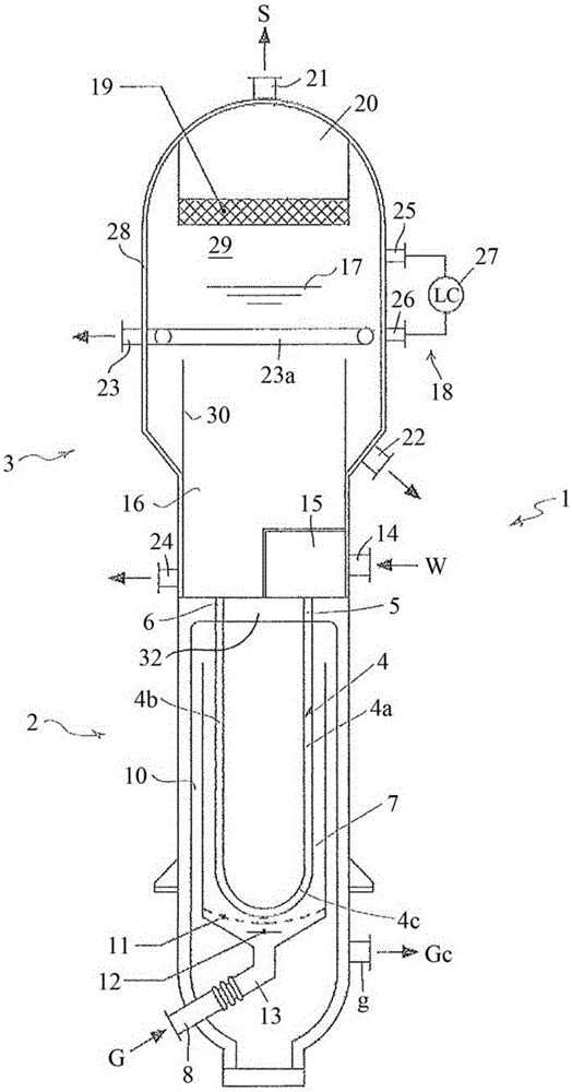
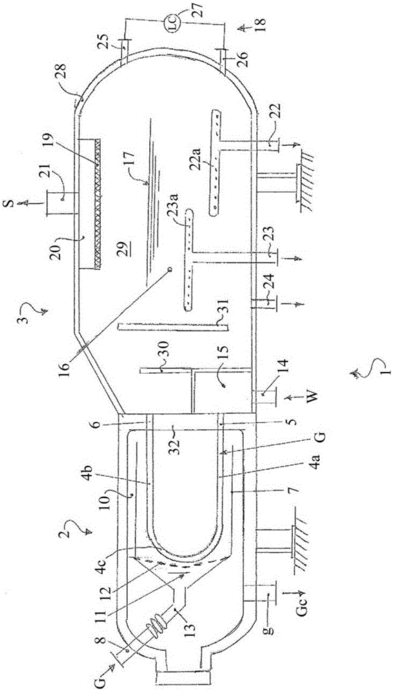
[0030] figure 1 A vertical shell and tube waste heat boiler 1 according to a preferred embodiment of the invention is shown.

[0031] Boiler 1 is designed to recover heat from hot gas G by heating and evaporating feed water W to generate steam S at a suitable pressure.

[0032] Said boiler 1 basically comprises a lower exchange section 2 embodied as a shell-and-tube heat exchanger and an upper separation section 3 receiving a mixed steam-water effluent from the tubes and designed to separate the steam from the non-evaporated water separate.

[0033] In more detail, the lower part 2 comprises a bundle of tubes 4 with respective tube inlet ends 5 and tube outlet ends 6 and a thermal chamber 7 surrounding said tubes 4 . This lower part 2 operates substantially as a shell and tube heat exchanger, where the tubes are fed with water W and hot gas G passes through the shell side (ie the thermal chamber 7 ).

[0034] The bundle of tubes is shown schematically. Each tube 4 is a U-s...


PUM


Abstract

A shell-and-tube apparatus (1), suitable for use as a waste heat boiler, comprising a vessel with an exchanging section (2) and a separating section (3), wherein: said exchanging section (2) contains a bundle of U-tubes (4) fed with an evaporable liquid medium such as water (W) and exposed to a hot gas (G) flowing in a hot chamber around said tubes, so that said medium is partially evaporated in the tubes while recovering heat from hot gas flowing in the hot chamber (7); said separating section (3) comprises a collection chamber (16) in communication with outlet of the tubes (4) to receive the partially evaporated medium leaving the tubes; said separating section (3) is arranged to provide separation of vapour fraction and liquid fraction from the partially evaporated medium at least partially by gravity; the apparatus also comprises means for controlling the liquid level in the collection chamber and for a partial recycle of the non-evaporated liquid.

Description

technical field [0001] The present invention relates to a shell and tube heat exchanger suitable for recovering heat from a process stream by evaporating a medium such as water. Such heat exchangers are commonly referred to as waste heat boilers (WHB). Background technique [0002] A common need in chemical and petrochemical plants is to recover heat from hot gases such as effluents of combustion processes or strongly exothermic reactions. Heat is usually recovered by evaporation of water at suitable pressure and generation of hot steam; the steam can be used internally in the process, where appropriate, to generate electricity or drive auxiliary equipment (such as compressors). [0003] Vertical shell and tube steam boilers are widely used in the prior art to meet this need. For example in a typical prior art vertical steam boiler, the hot gas flows in a U-shaped tube bundle arranged upwards and connected to the tube sheet at the bottom; the evaporation of water takes pla...

Claims


Application Information

Patent Timeline
Patent Type & Authority Applications(China)
IPC IPC(8): F22B1/18F22B21/02F22B37/26
CPCF22B1/1838F22B21/02F22B37/26F22B1/1884F22B21/30F22B35/007
Inventor 埃尔曼诺·菲利皮卢卡·雷达埃利
Owner CASALE SA
Learn More