Dispersion compensation method and apparatus

A dispersion compensation and dispersion value technology, which is applied in the optical field, can solve the problems of inability to recognize received data, decline in reception performance, and inability to lock the dispersion value on the receiving side of the optical module, so as to achieve normal and stable working performance and solve the problem of data interference. Effect

Active Publication Date: 2016-03-16
ZTE CORP
View PDF5 Cites 0 Cited by
  • Summary
  • Abstract
  • Description
  • Claims
  • Application Information

AI Technical Summary

Problems solved by technology

[0003] The system performance should be optimal when the dispersion value in the actual system is 0 ps / (nm×km), but due to the existence of noise, if the peak-to-peak value of the curve is used to represent the performance of the module under a specific dispersion value, the dispersion value will be obtained as The peak-to-peak value is the largest at 100ps / (nm×km), and finally the optimal dispersion operating point of the system is misconfigured to 100ps / (nm×km), which causes the receiving side of the optical module to fail to lock to the correct dispersion value, resulting in a decrease in receiving performance or The received data is unrecognizable

Method used


Image

  • Dispersion compensation method and apparatus
  • Dispersion compensation method and apparatus
  • Dispersion compensation method and apparatus

Examples


Embodiment 1

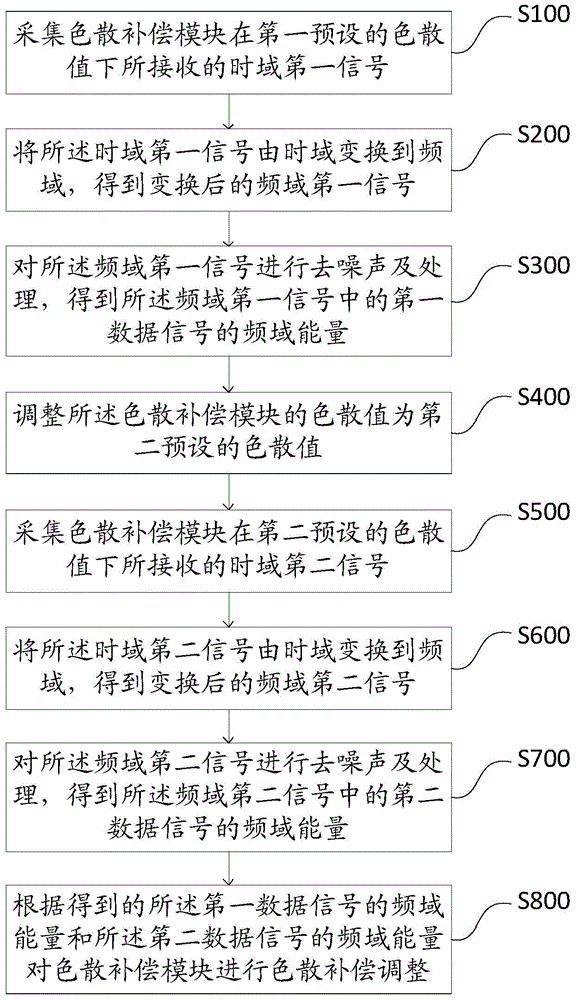
[0099] like figure 1 As shown, one of the flowcharts of the method for chromatic dispersion compensation in the first embodiment of the present invention, the method for chromatic dispersion compensation includes the following steps:

[0100] Step S100: Collect the time domain first signal received by the dispersion compensation module under the first preset dispersion value.

[0101] It should be noted that the actual signal transmission contains noise interference, and the received first signal in the time domain here contains noise interference.

[0102] Step S200: Transform the first signal in the time domain from the time domain to the frequency domain to obtain the transformed first signal in the frequency domain.

[0103] It should be noted that there are many methods for converting a signal from the time domain to the frequency domain. In the embodiment of the present invention, the discrete Fourier transform is used to transform the first signal in the time domain c...

Embodiment 2

[0155] like Figure 7 As shown, it is a schematic diagram of the application of the dispersion compensation method in the embodiment of the present invention to the dual subracks. The transmitting end of the subrack 1 is connected to the receiving end of the subrack 2 through the dispersion compensation module; The receiving end of rack 1 is connected; the connecting line between sub-rack 1 and sub-rack 2 is an optical fiber, and the working steps are as follows:

[0156] Step 1: Set the dispersion value of the dispersion compensation module to -700ps / (nm×km).

[0157] Step 2: The dispersion compensation module performs dispersion scanning on the receiving side to obtain the receiving performance curve.

[0158] Step 3: Perform discrete Fourier transform processing on the performance curve, and perform energy change processing to obtain a frequency domain energy curve.

[0159] Step 4: De-noise the frequency-domain energy curve, remove the energy of the noise part, obtain th...

Embodiment 3

[0163] like Figure 8 As shown, it is a schematic diagram of the application of the embodiment of the present invention in the remote transmission of the single subrack. When the remote signal needs to be transmitted to the receiving end of the device A1, the receiving end of the device A1 and the remote signal are connected by optical fibers, and the transmitting end of the device A1 is connected by optical fiber. not connected. After the optical fiber is connected, it does not need to be changed in future use. The specific steps of implementation are shown in the second embodiment.


PUM


Abstract

The invention provides a dispersion compensation method and device. The method comprises the steps of collecting a time domain first signal received by a dispersion compensation module at a first preset dispersion value and converting the time domain first signal into a frequency domain first signal; denoising and processing the frequency domain first signal and obtaining frequency domain energy of a first data signal; adjusting the dispersion value of the dispersion compensation module to be a second preset dispersion value; acquiring a time domain second signal received by the dispersion compensation module at the second preset dispersion value and converting the time domain second signal into a frequency domain second signal; denosing and processing the frequency domain second signal and obtaining frequency domain energy of a second data signal; and adjusting the dispersion compensation of the dispersion compensation module based on the frequency domain energy of the first data signal and the frequency domain energy of the second data signal. The invention determines an optimal dispersion point of the dispersion compensation module by filtering, denosing and processing a scanning signal, so that the whole module can work properly at an optimal dispersion value.

Description

technical field [0001] The present invention relates to the field of optical technology, and in particular, to a method and device for dispersion compensation. Background technique [0002] During the start-up process of the optical module, the dispersion value of the adjustable dispersion compensation module will be adjusted to make the entire module system work at the best dispersion point and ensure that the performance of the optical module is optimal at this dispersion value. The typical working process of the adjustable dispersion compensation module is as follows: Figure 21 As shown, control the tunable dispersion compensation module to scan from -700ps / (nm×km) to +700ps / (nm×km), and query the scan peak value each time, and set the TDC (tunablechromaticdispersioncompensation, tunablechromaticdispersioncompensation, hereinafter referred to as TDC) value. like Figure 22 As shown, the adjustable dispersion compensation module scans and increases the dispersion value ...

Claims


Application Information

Patent Timeline
IPC IPC(8): H04B10/2513
CPCH04B10/2513
Inventor 毛明旺
Owner ZTE CORP
Why Eureka
Try Eureka