Self-adaptive centrifugal speed reducer

A reducer and self-adaptive technology, applied in the mechanical field, can solve the problems of manual control, high cost, complex control, etc., and achieve the effect of automatic control

Active Publication Date: 2016-03-16
太仓天润新材料科技有限公司
View PDF6 Cites 5 Cited by
  • Summary
  • Abstract
  • Description
  • Claims
  • Application Information

AI Technical Summary

Problems solved by technology

[0004] The technical problem mainly solved by the present invention is to provide an adaptive centrifugal reducer, which can solve the problems of complex control, high cost or manual control of existing equipment by pushing the push rod to brake and decelerate during the centrifugal movement of the heavy hammer

Method used


Image

  • Self-adaptive centrifugal speed reducer

Examples


Embodiment Construction

[0014] The following will clearly and completely describe the technical solutions in the embodiments of the present invention. Obviously, the described embodiments are only some of the embodiments of the present invention, rather than all the embodiments. Based on the embodiments of the present invention, all other embodiments obtained by persons of ordinary skill in the art without making creative efforts belong to the protection scope of the present invention.

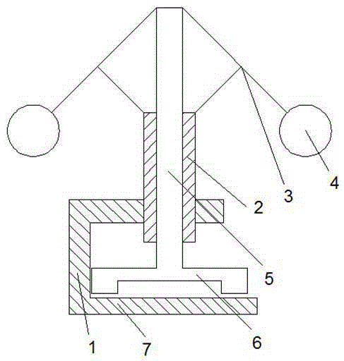
[0015] see figure 1 , the embodiment of the present invention includes:

[0016] An adaptive centrifugal reducer, comprising: a bracket 1, a rotating shaft 2, a rotating arm 3, a weight 4, a push rod 5, a brake pad 6, and a brake disc 7, the bracket 1 is fixed with a rotating shaft 2, A rotating arm 3 is fixed on the rotating shaft 2, a weight 4 is connected to the end of the rotating arm 3, and a push rod 5 is connected to the top of the rotating arm 3, and the pushing rod 5 is coaxially arranged with the rotating ...


PUM


Abstract

The invention discloses a self-adaptive centrifugal speed reducer. The self-adaptive centrifugal speed reducer comprises a bracket, a rotary shaft, rotary arms, heavy hammers, a pushing rod, a brake sheet and a brake disc, wherein the rotary shaft is rotationally fixed on the bracket; the rotary arms are fixed on the rotary shaft; the tail end of each rotary arm is connected with each heavy hammer; the top ends of the rotary arms are connected with the pushing rod; the pushing rod and the rotary shaft are coaxially arranged; the pushing rod passes through the center of the rotary shaft; the brake sheet is connected to the bottom of the pushing rod and is arranged on the brake disc. Through the self-adaptive centrifugal speed reducer, the pushing rod is pushed to brake and decelerate by the centrifugal movement of the heavy hammers; a rhombic four-connection-rod mechanism is used for converting the centrifugal force into pressure, so that the braking function is achieved; through adoption of the centrifugal force, the brake pressure changes along with the change of the rotation speed of equipment, so that the automatic control is achieved.

Description

technical field [0001] The invention relates to the mechanical field, in particular to an adaptive centrifugal reducer. Background technique [0002] Deceleration, also known as braking, refers to the action of stopping or reducing the speed of running locomotives, vehicles and other means of transport or machinery. The general principle of braking is to fix a wheel or disc on the high-speed shaft of the machine. The corresponding brake shoes, belts or discs are installed on the seat, and the braking torque is generated under the action of external force. The deceleration device is also a mechanical braking device that can slow down the speed of the vehicle. [0003] Brakes have important applications in many occasions, such as production equipment, vehicles, entertainment facilities, etc. The existing brakes are usually controlled by humans or directly locked by automatic equipment. Linear, inexpensive automatic control method. Contents of the invention [0004] The tec...

Claims


Application Information

Patent Timeline
Patent Type & Authority Applications(China)
IPC IPC(8): F16D43/10
CPCF16D43/10F16D2500/10481
Inventor 王吉雷顾云龙
Owner 太仓天润新材料科技有限公司
Why Eureka
Try Eureka