
a fuel catalyst

A fuel catalytic core and catalytic converter technology, applied in chemical instruments and methods, fuel re-atomization/homogenization, chemical elements of heterogeneous catalysts, etc. and other problems, to achieve the effect of increasing the calorific value of combustion, reducing engine wear and prolonging service life

Active Publication Date: 2018-02-16
GUANGZHOU NANSHU ELECTRONICS TECH CO LTD
View PDF5 Cites 0 Cited by
  • Summary
  • Abstract
  • Description
  • Claims
  • Application Information

AI Technical Summary

Problems solved by technology

[0002] At present, automobiles are an indispensable means of transportation in people's daily life. With the popularization and use of automobiles, the demand for fuel is increasing, resulting in a great waste of resources, and various exhaust emissions from fuel combustion are serious. Exceeding the standard, the air pollution is becoming more and more serious, which has brought great hidden dangers to people's health. Similarly, the use of fuel oil is indispensable for various industrial applications and large-scale hydraulic equipment. Fuel oil is an inherent non-renewable resource. Rationalization and maximization of the application effect is a major trend at present. It solves the problem of full combustion of fuel, and can then alleviate the imminent problems of resource consumption and waste and air pollution.
[0003] In view of the above problems, some research and development personnel have disclosed a Chinese patent titled "Method for Sufficient Combustion of Auxiliary Fuel Oil and Fuel-Saving Combustion Supporter" and the patent number is CN201410722833.9. The main body of the structure is equipped with a storage grid and a compression spring, and a combustion aid is provided in the storage grid. The combustion aid is composed of various metal components, including 30% to 35% of rare metals, 51% of Al2O3, 2.1% Fe and 8.0% Si, the rare metal is composed of any lanthanum, cerium, praseodymium, neodymium, promethium, samarium and europium, the above structure is in use, because it uses ceramic balls as a carrier, and then The catalyst is coated on the surface and then put into the housing. Due to the long-term vibration of the engine, the ceramic balls will continue to rub against each other, the surface catalyst coating is easy to fall off, and the catalytic effect will gradually fail. The blockage of the oil circuit will seriously cause engine damage, affect normal use, and affect catalytic efficiency; and the structure is complex and the installation is not convenient enough

Method used


Image

  • a fuel catalyst
  • a fuel catalyst
  • a fuel catalyst

Examples


Embodiment 1

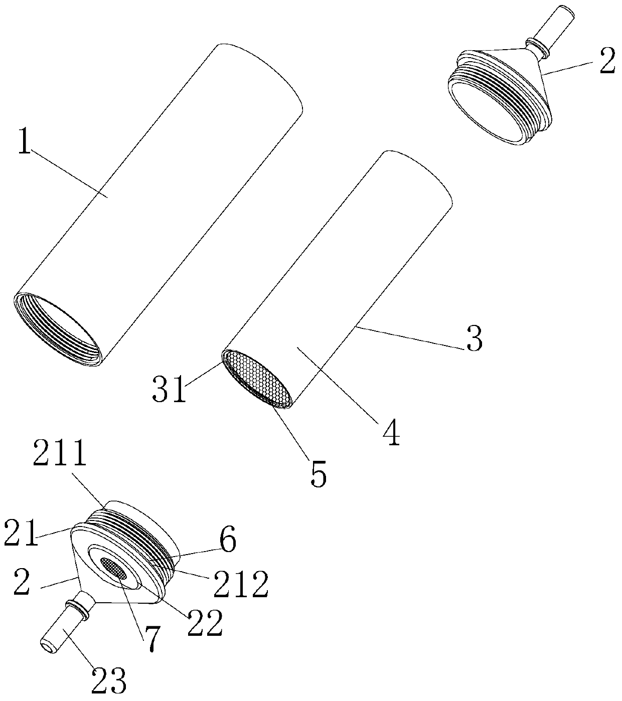
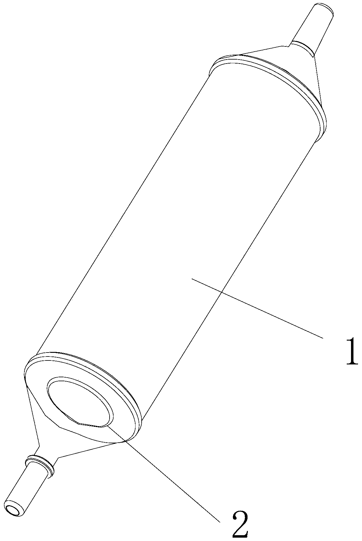
[0041] as attached Figure 1-3 As shown, a fuel catalytic converter includes a structural main body 1, the structural main body 1 is a hollow columnar structure, the two ends of the structural main body 1 are respectively provided with a cover 2, and the cover 2 is provided with an oil pipe connection Port 23, the structural main body 1 is provided with a hollow carrier shell 3, the carrier shell 3 is filled with a fuel catalyst core 4, the fuel catalyst core 4 includes a honeycomb catalyst carrier 5, and the surface of the honeycomb catalyst carrier 5 is Coated with fuel catalyst. When in use, the fuel catalyst is connected to the outside of the engine. After the fuel enters the fuel catalyst, the flow channel on the honeycomb catalyst carrier divides the fuel and fully contacts the fuel catalyst. The unique material characteristics of the fuel catalyst are used to refine and catalyze the increase of fuel oil. The fuel is active, so that the fuel molecular clusters can produ...

Embodiment 2

[0055] as attached Figure 1-3 As shown, a fuel catalytic converter includes a structural main body 1, the structural main body 1 is a hollow columnar structure, the two ends of the structural main body 1 are respectively provided with a cover 2, and the cover 2 is provided with an oil pipe connection Port 23, the structural main body 1 is provided with a hollow carrier shell 3, the carrier shell 3 is filled with a fuel catalyst core 4, the fuel catalyst core 4 includes a honeycomb catalyst carrier 5, and the surface of the honeycomb catalyst carrier 5 is Coated with fuel catalyst.

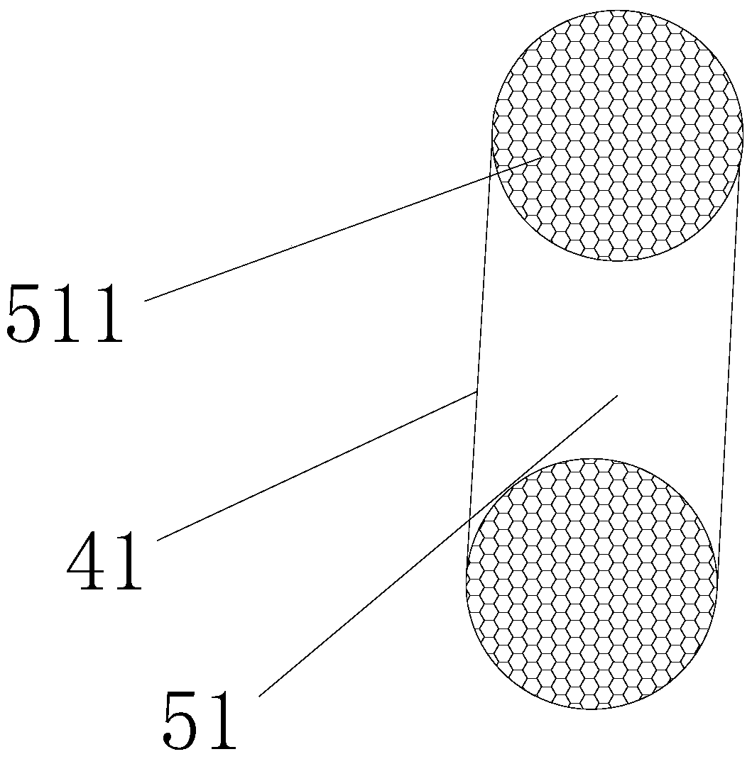
[0056] Preferably, the fuel catalyst core 4 is a honeycomb metal fuel catalyst core 41, and the honeycomb metal fuel catalyst core 41 adopts a honeycomb metal catalyst carrier 51.

[0057] Compared with Example 1, the difference is that the preparation process of the fuel catalytic core 4 is different,

[0058] The preparation process of the fuel catalytic core 4 comprises the following steps: ...

Embodiment 3

[0066] as attached Figure 1-3 As shown, a fuel catalytic converter includes a structural main body 1, the structural main body 1 is a hollow columnar structure, the two ends of the structural main body 1 are respectively provided with a cover 2, and the cover 2 is provided with an oil pipe connection The main body 1 of the port 23 is provided with a hollow carrier shell 3, and the carrier shell 3 is filled with a fuel catalytic core 4, and the fuel catalytic core 4 includes a honeycomb catalyst carrier 5, and the surface of the honeycomb catalyst carrier 5 is coated with Covered with fuel catalyst.

[0067] Preferably, the fuel catalyst core 4 is a honeycomb metal fuel catalyst core 41, and the honeycomb metal fuel catalyst core 41 adopts a honeycomb metal catalyst carrier 51.

[0068] Compared with Example 1, the difference is that the preparation process of the fuel catalytic core 4 is different,

[0069] The preparation process of the fuel catalytic core 4 comprises the ...


PUM


Abstract

The invention relates to the technical field of fuel catalytic devices, and in particular to a fuel catalytic converter, which includes a structural main body, which is a hollow columnar structure. Covers are provided at both ends of the structural main body, and oil pipe connection ports are provided on the cover. The structure The main body is equipped with a hollow carrier shell, and the carrier shell is filled with a fuel catalytic core. The fuel catalytic core includes a honeycomb catalyst carrier, and the surface of the honeycomb catalyst carrier is coated with a fuel catalyst. The fuel catalytic core uses a honeycomb catalyst carrier, and the honeycomb structure is regular. The fine pores evenly distribute and catalyze the fuel, and the effect is stable and long-lasting. The honeycomb catalyst carrier is coated with a fuel catalyst, which has a unique structure. The contact area between the fuel and the fuel catalyst is large, reducing fuel consumption by 15-20%, and effectively reducing the original vehicle fuel rate. ; It can increase power by 15-25%, shorten braking distance, and reduce exhaust pollutants by more than 50%. The catalyst will not fall off or be clogged, and fuel can pass smoothly. It has a simple structure and is easy to install.

Description

technical field [0001] The invention relates to the technical field of fuel catalytic devices, in particular to a fuel catalytic converter. Background technique [0002] At present, automobiles are an indispensable means of transportation in people's daily life. With the popularization and use of automobiles, the demand for fuel is increasing, resulting in a great waste of resources, and various exhaust emissions from fuel combustion are serious. Exceeding the standard, the air pollution is becoming more and more serious, which has brought great hidden dangers to people's health. Similarly, the use of fuel oil is indispensable for various industrial applications and large-scale hydraulic equipment. Fuel oil is an inherent non-renewable resource. Rationalization and maximization of the application effect is a major trend at present. It solves the problem of full combustion of fuel, and can then alleviate the imminent problems of resource consumption and waste and air pollutio...

Claims


Application Information

Patent Timeline
Patent Type & Authority Patents(China)
IPC IPC(8): B01J19/24B01J23/10B01J35/04F02M29/04
CPCB01J19/248F02M29/04B01J23/002B01J23/10B01J2219/2434B01J2219/2428B01J2219/2402B01J2523/00B01J35/56B01J2523/3725B01J2523/3706B01J2523/3712B01J2523/47B01J2523/31
Inventor 李继成
Owner GUANGZHOU NANSHU ELECTRONICS TECH CO LTD
Learn More