
Valve drying box

A technology for drying boxes and valves, applied in drying, drying machines, drying chambers/containers, etc., can solve problems such as rusting and affecting work efficiency, and achieve the effect of improving drying efficiency and ensuring production efficiency

Inactive Publication Date: 2016-03-09
WUHU JIENUO TECH
View PDF10 Cites 1 Cited by
  • Summary
  • Abstract
  • Description
  • Claims
  • Application Information

AI Technical Summary

Problems solved by technology

[0004] In order to prevent the valve from rusting, the valve will be sprayed with a layer of paint before leaving the factory, and then the valve will be air-dried. Under the high-efficiency requirements of modern production, the traditional air-drying method cannot meet the requirements of modern production. to dry
The existing drying device requires complex opening and closing actions every time it is opened and sealed. Opening the cabinet door of the drying box and closing the cabinet door of the drying box seriously affect the work efficiency

Method used


Image

  • Valve drying box
  • Valve drying box

Examples


Embodiment Construction

[0014] In order to make the technical means and creative features realized by the present invention easy to understand, the present invention will be further elaborated below.

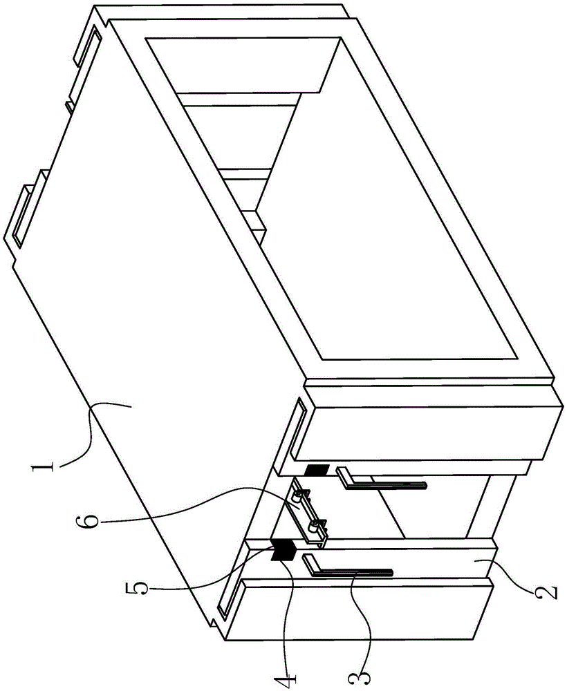
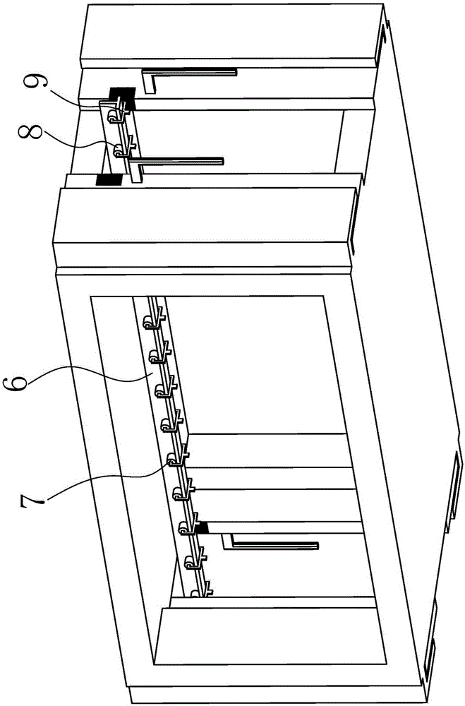
[0015] Such as Figure 1 to Figure 2 As shown, a valve drying box includes a box chamber 1, and the left and right sides of the box chamber 1 are provided with side-pull movable doors 2, and the side-pull movable doors 2 on each side are of a split type. The outer end face of the pull-type dodge door 2 is provided with L-shaped handles 3, and the handle 3 can be set longer to prevent the heat in the chamber 1 from being transferred to the end of the handle 3. The side-pull dodge door 2 Grooves 4 are provided on the side contacting with the other side pull-type movable door 2, and curtains 5 made of asbestos materials are evenly distributed in the grooves 4.

[0016] A crossbeam 6 is horizontally arranged in the chamber 1, and the crossbeam 6 is in the shape of an inverted T. Hangers 7 are evenly hung ...


PUM


Abstract

The invention relates to a valve drying box. The valve drying box comprises a box room; side-pulling-type mobile gates are arranged on the left and right sides of the box room; the side-pulling-type mobile gates on each side are opposite-opening-type; the outer end surface of each side-pulling-type movable gate is provided with an L-shaped pulling handle; the side face, which is in contact with the side-pulling-type movable gate on the other side, of each side-pulling-type movable gate is provided with a groove; and a curtain made of an asbestos material is arranged in each groove. According to the valve drying box, the upper parts of the side-pulling-type movable doors on the left and right sides of the box room are separately provided with a groove used for receiving a cross beam; the curtains on the grooves can flexibly block the two sides of the cross beam, so that heat in the box room is prevented from flowing outwards; energy conservation and emission reduction are facilitated; the drying efficiency of valves is improved; the opening and closing of the box room are not affected; and the production efficiency can be ensured.

Description

technical field [0001] The invention relates to the technical field of valve surface drying equipment, in particular to a valve drying box. Background technique [0002] The valve is a control component in the fluid delivery system, which has functions such as cut-off, adjustment, flow diversion, reverse flow prevention, pressure stabilization, flow diversion or overflow pressure relief. [0003] Valves used in fluid control systems range from the simplest cut-off valves to various valves used in extremely complex automatic control systems, with a wide variety of varieties and specifications. Valves can be used to control the flow of various types of fluids such as air, water, steam, various corrosive media, mud, oil, liquid metal and radioactive media. [0004] In order to prevent the valve from rusting, the valve will be sprayed with a layer of paint before leaving the factory, and then the valve will be air-dried. Under the high-efficiency requirements of modern producti...

Claims


Application Information

Patent Timeline
Patent Type & Authority Applications(China)
IPC IPC(8): F26B9/06F26B25/12
CPCF26B9/06F26B25/12
Inventor 鲁明鲁传玉鲁俊
Owner WUHU JIENUO TECH
Learn More