
Ethernet transmission line

A network transmission and transmission line technology, applied in the direction of network connectors, connections with four or more poles, coupling devices, etc., can solve problems such as excessive size, increased cost, and aesthetic impact

Inactive Publication Date: 2020-08-11
ASKEY COMP
View PDF2 Cites 0 Cited by
  • Summary
  • Abstract
  • Description
  • Claims
  • Application Information

AI Technical Summary

Problems solved by technology

[0003] Ethernet is a main way of wired transmission of computer network, however, the wire diameter or thickness of known Ethernet wires are all too large (mostly all exceed 1.5mm), specifically, the Ethernet wire with twisted pair In other words, multiple twisted pairs are wound around each other. In addition to conductive lines (such as copper wires), each pair of wires has an insulating layer on the outside of the conductive line, and multiple twisted pairs are wrapped with protective skin after winding. , so that the diameter or thickness of the Ethernet cable cannot be further reduced. Therefore, if the Ethernet cable needs to be connected to an outdoor unit, additional construction (such as destroying doors or windows or drilling holes in the wall) is required for wiring operation, resulting in increased costs and damage to the interior decoration and affect the appearance

Method used


Image

  • Ethernet transmission line
  • Ethernet transmission line
  • Ethernet transmission line

Examples


Embodiment Construction

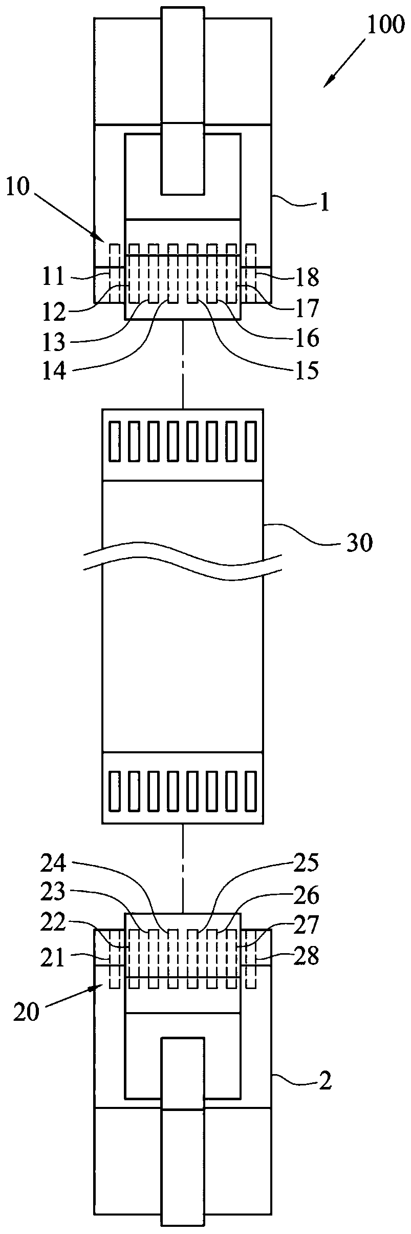
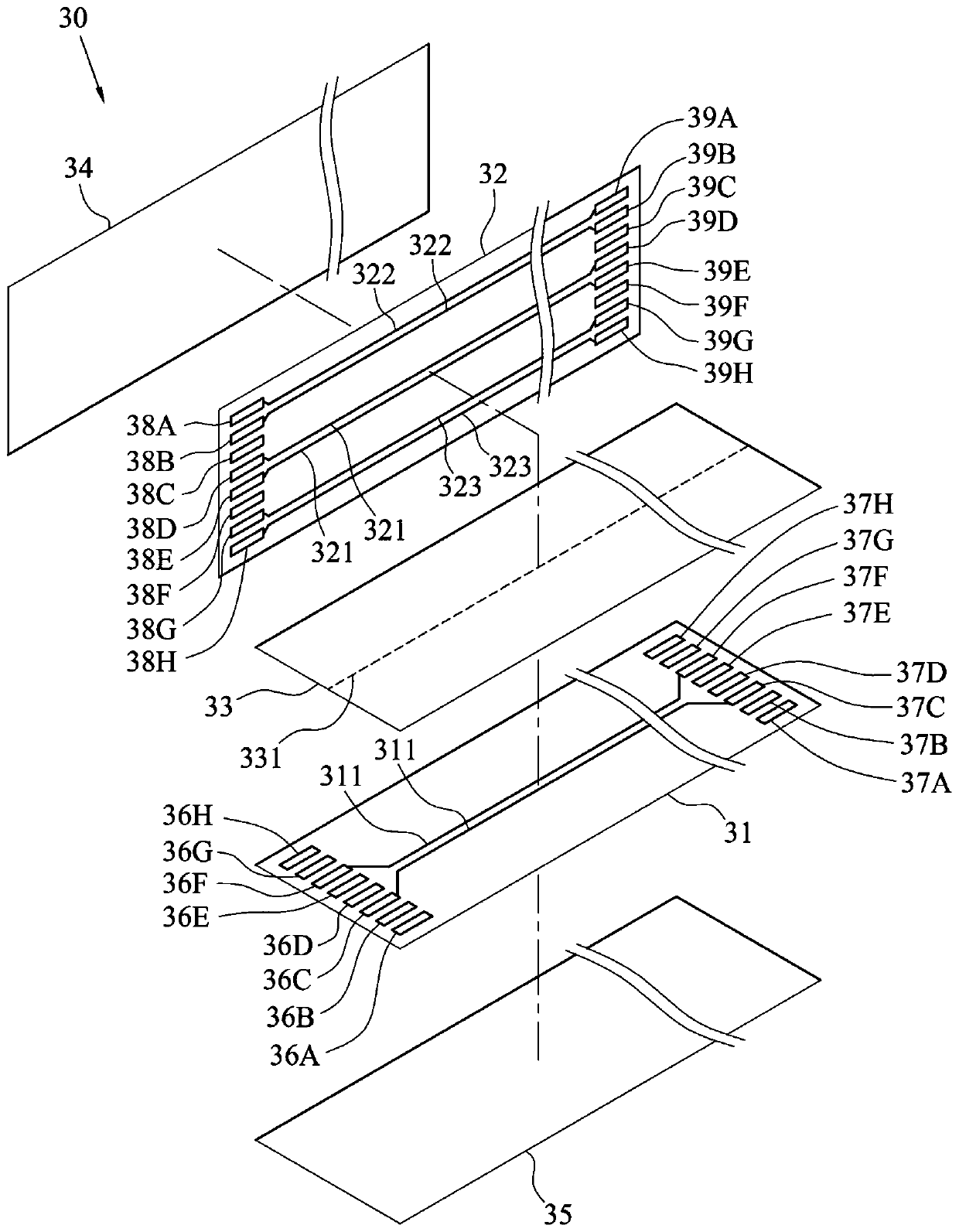
[0048] like figure 1 As shown, the Ethernet transmission line 100 includes two RJ45 connectors and a thin connection cable 30 , wherein the thin connection cable 30 is connected between the two RJ45 connectors (hereinafter referred to as the first RJ45 connector 1 and the second RJ45 connector 2 ). like figure 2 As shown, the first RJ45 connector 1 and the second RJ45 connector 2 have connection terminal groups 10 and 20 respectively, and the connection terminal group 10 of the first RJ45 connector 1 includes a first terminal 11, a second terminal 12, and a third terminal arranged in sequence. Terminal 13 , fourth terminal 14 , fifth terminal 15 , sixth terminal 16 , seventh terminal 17 and eighth terminal 18 . The connecting terminal group 20 of the second RJ45 connector 2 includes a first terminal 21, a second terminal 22, a third terminal 23, a fourth terminal 24, a fifth terminal 25, a sixth terminal 26, a seventh terminal 27 and Eighth terminal 28 . In some embodiment...


PUM


Abstract

T he invention relates to an Ethernet transmission line. The Ethernet transmission line comprises two RJ45 connectors and a thin connecting line, wherein each RJ45 joint is provided with a connectingterminal group, the connecting terminal group comprises a first terminal, a second terminal, a third terminal, a fourth terminal, a fifth terminal, a sixth terminal, a seventh terminal and an eighth terminal which are arranged in sequence, the first terminal and the second terminal are a first pair of differential terminals, the third terminal and the sixth terminal are a second pair of differential terminals, the fourth terminal and the fifth terminal are a third pair of differential terminals, and the seventh terminal and the eighth terminal are a fourth pair of differential terminals, the thin connecting wire is connected between the two RJ45 joints, the thin connecting line comprises a first flexible circuit board layer, a second flexible circuit board layer and a spacing layer, the spacing layer is clamped between the first flexible circuit board layer and the second flexible circuit board layer, the first flexible circuit board layer is provided with two first transmission lines,the two first transmission lines are electrically connected with the third terminals and the sixth terminals corresponding to the connecting terminal groups respectively, the second flexible circuitboard layer is provided with two second transmission lines, and the two second transmission lines are electrically connected with the fourth terminals and the fifth terminals corresponding to the connecting terminal groups respectively.

Description

technical field [0001] The present invention relates to a transmission line, in particular to an Ethernet transmission line. Background technique [0002] With the maturity and popularization of communication technology, network connection has become an indispensable part of most institutions, families and individuals. Generally speaking, most people will install a network sharer indoors, so that multiple communication devices (such as laptops, smart phones or tablet computers) within a certain range can connect to the network Internet sharer connected to the Internet. [0003] Ethernet is a main way of wired transmission of computer network, however, the wire diameter or thickness of known Ethernet wires are all too large (mostly all exceed 1.5mm), specifically, the Ethernet wire with twisted pair In other words, multiple twisted pairs are wound around each other. In addition to conductive lines (such as copper wires), each pair of wires has an insulating layer on the out...

Claims


Application Information

Patent Timeline
Patent Type & Authority Applications(China)
IPC IPC(8): H01R31/06H01B7/00H01B7/08H01B7/17H01B11/00
CPCH01R31/06H01B11/00H01B7/17H01B7/0045H01B7/0009H01B7/0807H01R2201/04H01R24/64H01R2107/00H05K1/118H01R13/5202H01R12/777H05K3/4635H05K2201/10356H05K1/0245H05K2201/09672H05K3/281H05K1/0393H05K2201/0715H05K2201/10189H05K2201/10446H05K3/403H01B7/06H01R12/79H01R13/24H01R13/52H05K1/189
Inventor 魏崇闵
Owner ASKEY COMP
Learn More