Eureka AIR delivers breakthrough ideas for toughest innovation challenges, trusted by R&D personnel around the world.

A toughened glass cutting device adopting an abrasive blasting mode

A tempered glass and cutting device technology, which is applied in glass cutting devices, glass production, glass manufacturing equipment, etc., can solve the problems of difficult to change the nozzle correctly, cannot guarantee the precise cutting size, incorrect nozzle position, etc., and achieve shortening and adjusting the nozzle position time, improve product reliability, and increase production yield

Inactive Publication Date: 2016-03-09
TAE SUNG ENG
View PDF4 Cites 1 Cited by
  • Summary
  • Abstract
  • Description
  • Claims
  • Application Information

AI Technical Summary

Problems solved by technology

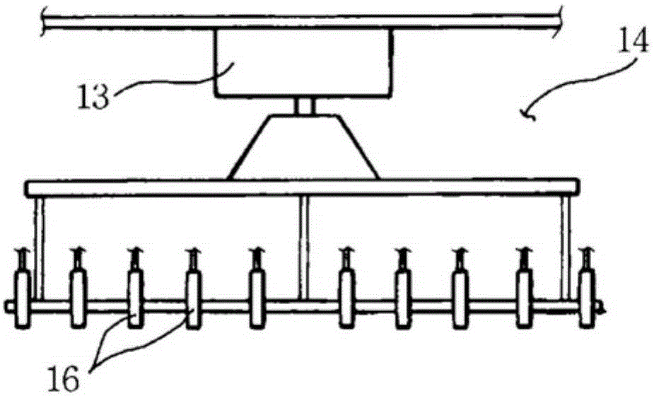
[0007] but if image 3 As shown, the setting position of the nozzle used for the tempered glass cutting device adopting the sandblasting method in the past remains fixed, therefore, only the cutting operation of cutting the workpiece into the size according to the fixed position of the nozzle 16 can be realized, and there is problem of limited size
[0008] Also, in order to adjust the cutting size, the nozzle unit needs to be replaced with another different nozzle unit, which is troublesome
[0009] In addition, the position of the nozzle can be changed manually, but in this case, it is difficult to change the position of the nozzle correctly, and also, the precise cutting size cannot be guaranteed due to the incorrect position of the nozzle

Method used


Image

  • A toughened glass cutting device adopting an abrasive blasting mode
  • A toughened glass cutting device adopting an abrasive blasting mode
  • A toughened glass cutting device adopting an abrasive blasting mode

Examples


Embodiment Construction

[0048] Hereinafter, preferred embodiments of the present invention will be described with reference to the drawings (the same reference numerals are used to designate the same structures as in the past, and detailed description thereof will be omitted).

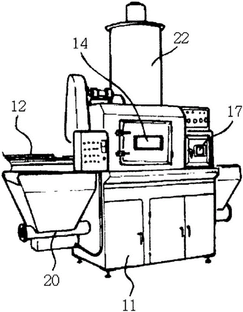
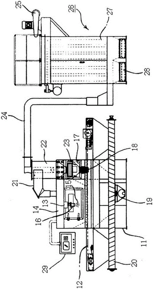
[0049] The tempered glass cutting device adopting the sandblasting method of the present invention includes: a main body 11; a conveyor unit 12, which transfers the workpiece 1 to the main body 11; a chamber 14, which is arranged in the middle of the conveyor unit 12 in a sealed manner part, cutting the workpiece 1 in the chamber 14; the nozzle unit is arranged in the chamber 14 to perform the cutting operation of cutting the workpiece 1 in the X-axis and Y-axis directions; the driving unit , to provide a driving force so that the nozzle unit is moved to the X-axis or Y-axis direction; the sensor unit senses to change the position of the nozzle that is arranged in the nozzle unit; and the clean room 17 is arranged in the One ...


PUM


Abstract

The invention relates to a toughened glass cutting device adopting an abrasive blasting mode. By freely adjusting the positions of a plurality of fixing blocks arranged on nozzle units to be the positions expected by users, the nozzle units are made to respectively and precisely move to designated positions. According to the invention, enabling the nozzle units to respectively move to designated positions corresponding to the sizes of displays can shorten time spent on nozzle position adjusting, and correct position moving can be realized since the positions of the fixing blocks of the nozzle units are sensed by sensor units. By freely adjusting the positions of the nozzle units, the displays of different sizes can be simultaneously processed. Accordingly, the toughened glass cutting device has advantages of an increased product production rate, an increased production yield and improved product reliability.

Description

technical field [0001] The present invention relates to a tempered glass cutting device using a sandblasting method, and more particularly, to a device for achieving extremely high production yields by precisely changing the fixed position of a fixed block arranged in a nozzle unit to a position desired by the user. Dahua adopts sandblasting tempered glass cutting device. Background technique [0002] Generally speaking, the tempered glass cutting device used as the sandblasting machine (AirSandBlastMachine) for cutting the tempered glass is to spray metal or non-metal materials such as abrasive (Media) or coarse sand (Grit) to the edge of the processed object at high speed. And the equipment for processing the processed objects. [0003] Such as Figure 1 to Figure 3 As shown, the conventional tempered glass cutting device adopting the sandblasting method includes: a main body 11; a conveyor unit 12 arranged on the main body 11 to transfer the processed object 1; a chamber...

Claims


Application Information

Patent Timeline
IPC IPC(8): C03B33/00
CPCY02P40/57
Inventor 郑孝才黃明秀李康得沈愚益
Owner TAE SUNG ENG
Why Eureka
Eureka Blog
Learn More