
Apparatus and method for sequential melting and refining in a continuous process

A process chamber, heat treatment technology, used in chemical instruments and methods, lighting and heating equipment, silicon compounds, etc.

Inactive Publication Date: 2016-03-02
ALD VACUUM TECH GMBH
View PDF5 Cites 2 Cited by
  • Summary
  • Abstract
  • Description
  • Claims
  • Application Information

AI Technical Summary

Problems solved by technology

In the second step, it may be necessary to apply high vacuum to remove volatile impurities
Electromagnetically manipulated flow is not mentioned

Method used


Image

  • Apparatus and method for sequential melting and refining in a continuous process
  • Apparatus and method for sequential melting and refining in a continuous process
  • Apparatus and method for sequential melting and refining in a continuous process

Examples


Embodiment Construction

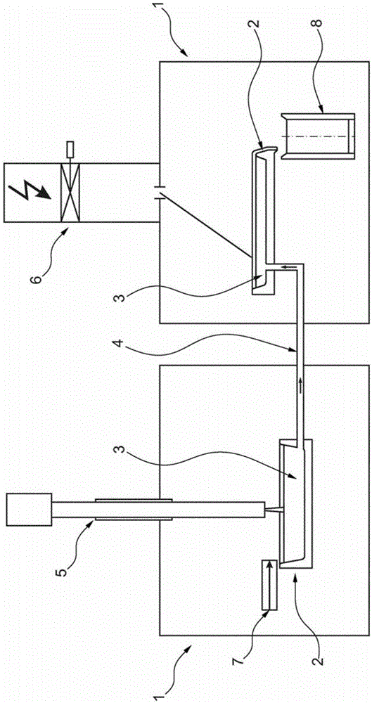
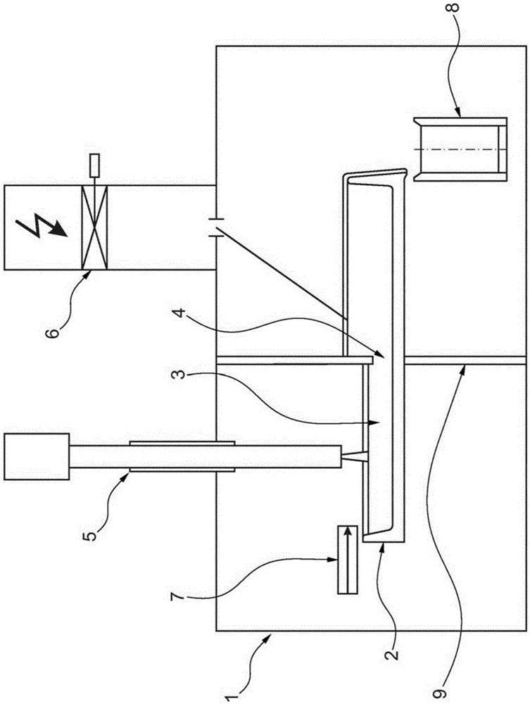
[0049] figure 1 A device according to the invention is shown comprising two process chambers 1 and two process containers 2 . As can be seen in the figure, each treatment chamber 1 contains a treatment vessel 2 . The material 3 to be treated present in the treatment container needs to be liquid, at the latest when it enters the conveying channel 4 . The two heat sources 5 and 6 shown are different. The heat source 5 may be, for example, a plasma burner and the heat source 6 may be, for example, an electron beam gun. It can be seen from the figure that the height of the liquid material in the second processing chamber is higher than that in the first processing chamber. Therefore, the liquid material has to be raised in the transfer channel 4 . This is caused by a pressure difference, since the plasma burner operates in the low pressure range in this embodiment, while the electron beam gun operates in a vacuum. Arrows show the flow direction of the liquid material. The li...


PUM

PropertyMeasurementUnit
melting pointaaaaaaaaaa

Abstract

An apparatus and a method performable with the apparatus for sequential melting and refining of materials are proposed. The materials treated in the process are converted to a liquid state of matter by heat sources. The process is particularly suitable for treating metals, semimetals and ceramics, for example in order to produce alloys and / or to refine the materials. During the method, the material goes through various treatment chambers which enable treatment at different pressure levels.

Description

technical field [0001] The present invention relates to an apparatus for sequentially melting and refining materials, and to a method carried out by said apparatus. During this process the material being processed is converted to a liquid substance by one or more heat sources, or the material was already in a liquid state prior to this processing. The method is particularly suitable for processing metals, non-metals and ceramics, for example in order to produce alloys and / or refine materials. Background technique [0002] Materials can be heated in a number of ways known from the prior art. One such method is the electron beam method, in which a beam of electrons is directed onto a material to generate heat in the material in a targeted manner. This method is particularly flexible because a certain part of the material can be heated to very high temperatures in a targeted manner. If a larger portion of the material should be heated, the electron beam can scan the entire m...

Claims


Application Information

Patent Timeline
Patent Type & Authority Applications(China)
IPC IPC(8): C22B9/04C01B33/03
CPCC22B9/04C01B33/037F27B19/00F27D27/00C22B9/228C22B9/226F27B19/02F27D3/14F27D11/06F27D11/08F27D11/12H01J37/305H01J37/32009
Inventor 亨利克·弗朗茨阿诺·尼卜林乌尔里希·布里歇尔
Owner ALD VACUUM TECH GMBH
Learn More