
touch panel

A touch panel and touch area technology, which is applied in the input/output process of instruments, electrical digital data processing, data processing, etc. Effect

Active Publication Date: 2018-08-14
TPK TOUCH SYST XIAMEN
View PDF4 Cites 0 Cited by
  • Summary
  • Abstract
  • Description
  • Claims
  • Application Information

AI Technical Summary

Problems solved by technology

[0005] The purpose of the present invention is to solve the problem that the transmission line of the conventional touch panel occupies a large area. The present invention proposes a new touch panel structure, and reasonably sets the position of the transmission line to maximize the touch area of ​​the touch panel.

Method used


Image

  • touch panel
  • touch panel
  • touch panel

Examples


Embodiment Construction

[0061] The present invention will be further described in detail below in conjunction with the accompanying drawings and specific embodiments.

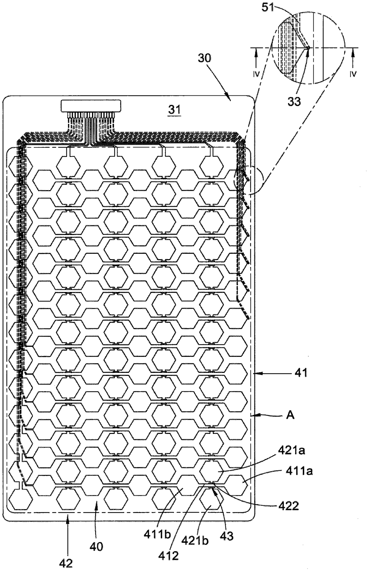
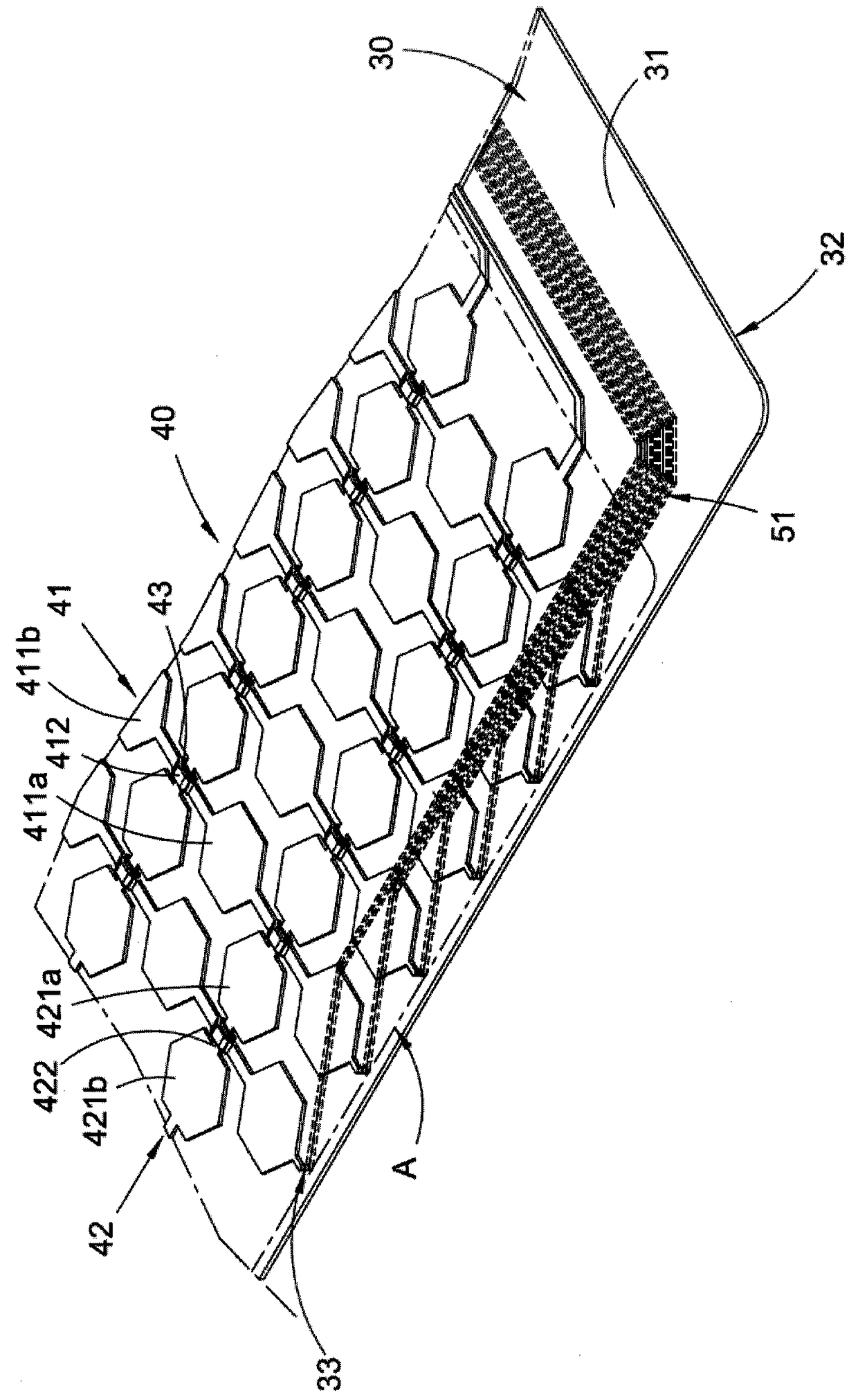
[0062] see figure 2 , image 3 and Figure 4 , shows a plan view, a perspective view of a partial structure, and a cross-sectional view of a partial structure of an embodiment of the touch panel of the present invention. An embodiment structure of the touch panel of the present invention includes: a transparent substrate 30, a touch electrode 40 and a transmission line for electrically connecting to the touch electrode 40. , wherein the transmission line arranged on the back side 32 of the transparent substrate 30 is called the first transmission line 51, and the transmission line arranged on the front side 31 of the transparent substrate 30 is called the second transmission line 52 (see Figure 7 to Figure 10 ), the first transmission line 51 is electrically connected to the touch electrode 40 through the conductive hole 33 , and...


PUM


Abstract

The invention discloses a touch panel. The touch panel is provided with a touch area; the touch panel comprises a transparent substrate, a touch electrode and a first transmission line, wherein at least one conductive hole is formed in the transparent substrate; the touch electrode is laid on the front surface of the transparent substrate and positioned in the touch area; and the first transmission line is laid on the back surface of the transparent substrate and electrically connected with the touch electrode through the conductive hole. According to the touch panel, by arranging at least part of the transmission line, that is laid on the transparent substrate, on the other side surface opposite to the touch electrode, the wiring flexibility of the transmission line can be improved; and in addition, the touch panel has the advantages and effects of reducing the wiring area of the touch panel and expanding the touch area of the touch panel.

Description

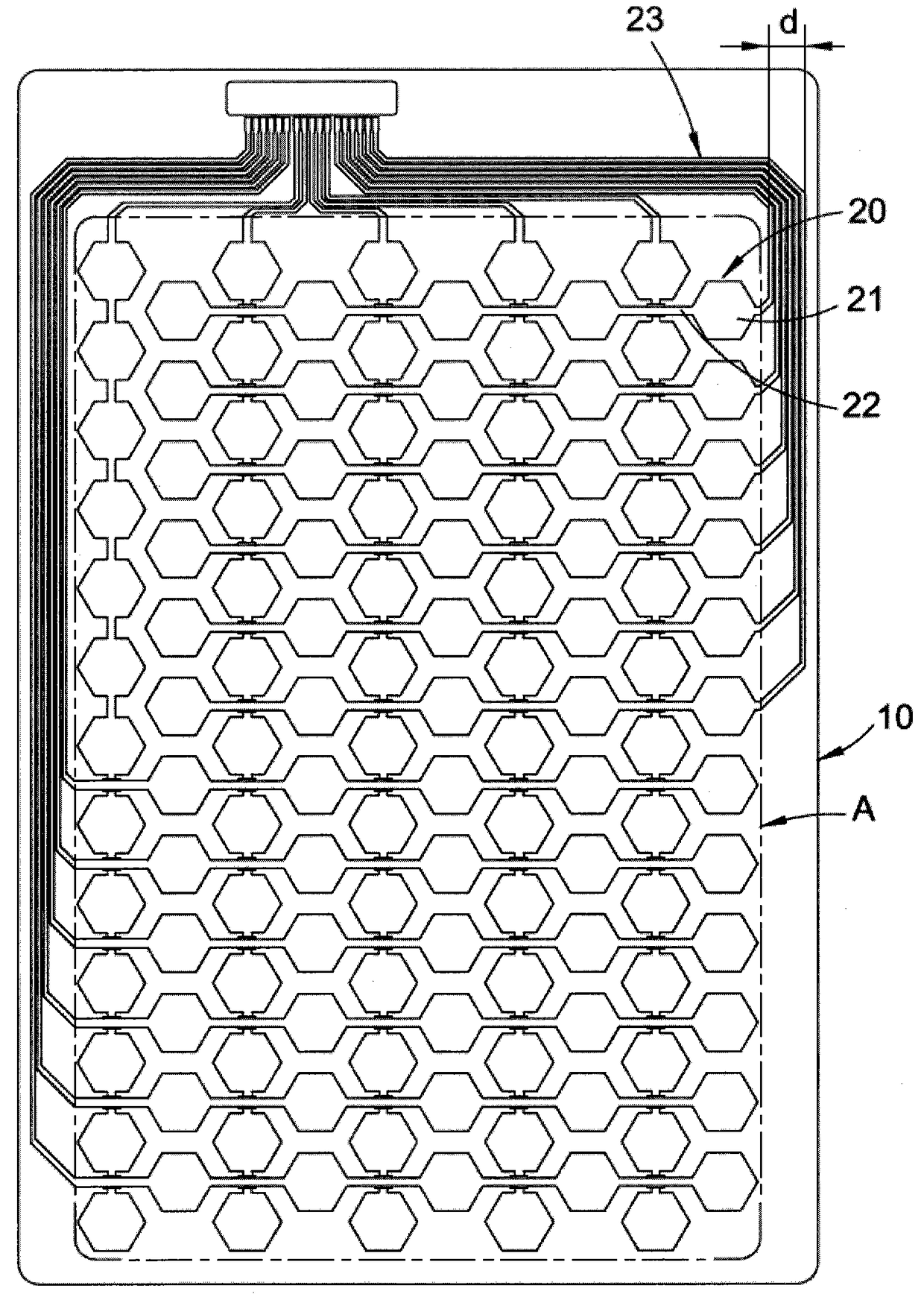
technical field [0001] The invention relates to the field of touch technology, in particular to a touch panel. Background technique [0002] An example of an existing touch panel structure is figure 1 As shown, it includes: a transparent substrate 10, a touch electrode 20 arranged on the surface of the transparent substrate 10, and a transmission line 23 (trace) electrically connected to the touch electrode 20; the touch electrode 20 is usually made of a transparent conductive oxide film material (Usually use indium tin oxide ITO) to form a certain pattern of touch electrodes 20 through coating etching. The touch electrodes 20 include a plurality of sensing units 21 (sensors) evenly distributed on the surface of the transparent substrate 10 Connecting wires 22 between measuring units 21. [0003] Taking the existing capacitive touch panel as an example, the capacitive touch panel works by using the current induction between the human body and the sensing electrodes 20 . W...

Claims


Application Information

Patent Timeline
Patent Type & Authority Patents(China)
IPC IPC(8): G06F3/041G06F3/044
Inventor 党一为方钦雪张普欣许婧
Owner TPK TOUCH SYST XIAMEN
Learn More