Disturbance Estimation Method for Gyro Flywheel System Based on Extended High Gain Observer
A technology of high-gain observer and gyro flywheel, applied in the field of inertial navigation
- Summary
- Abstract
- Description
- Claims
- Application Information
AI Technical Summary
Problems solved by technology
Method used
Image

Examples
specific Embodiment approach 1
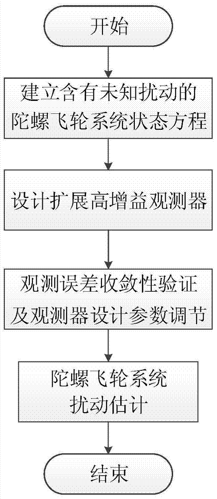
[0083] Specific implementation manner 1: The disturbance estimation method of the gyro flywheel system based on the extended high-gain observer of this embodiment is implemented according to the following steps:
[0084] Step 1: According to the dynamic equation of the gyro flywheel system, establish the state equation of the gyro flywheel system with unknown disturbance;
[0085] Step 2: According to the state equation of the gyro flywheel system with unknown disturbances, design an extended high gain observer;
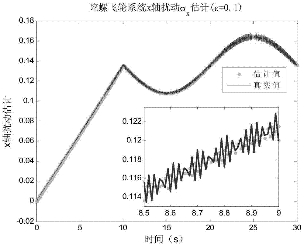
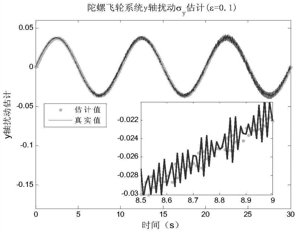
[0086] Step 3: Observation error convergence and observer design parameter ε adjustment;
[0087] Step four, realize the disturbance estimation of the gyro flywheel system.
specific Embodiment approach 2
[0088] Embodiment 2: The difference between this embodiment and Embodiment 1 is that it is characterized in that the state equation of the gyro flywheel system with unknown disturbance in step 1 is implemented in the following steps:
[0089] The tilt angle of the rotor of the gyro flywheel in two dimensions (φ x ,φ y ) And inclination angular velocity As the state variable x: Then the state equation of the gyro flywheel system with unmodeled disturbance is shown in formula (1):
[0090]
[0091] The measurement equation is shown in formula (2):
[0092]
[0093] Where f 1 (x,t),f 2 (x,t) represents the nonlinear mechanism term of the gyro flywheel under ideal conditions; u x ,u y Represents the control torque of the two-dimensional torque device, g x1 (x,t),g x2 (x,t),g y1 (x,t),g y2 (x, t) represents the nonlinear coefficient term of the two-dimensional torque device;
[0094] σ x (x,t),σ y (x,t) represents the unmodeled disturbance term of the system; y 1 ,y 2 Respectively represe...
specific Embodiment approach 3
[0116] Specific implementation manner 3: This implementation manner is different from specific implementation manners one or two in that it is characterized in that the design of the extended high gain observer in the second step is implemented in the following steps:
[0117] The measurement equation y=Cx is used to realize the control of the state variable x and the nonlinear disturbance term σ d The estimation of (x,t) is designed as follows to extend the high gain observer:
[0118]
[0119] among them, Is the state variable of the high gain observer; To expand the state variable of the high gain observer;
[0120] H(ε), F(ε) are the gain matrix of the observer, and its specific form is as follows:
[0121]
[0122] Among them, the design parameter ε> 0 is a small design parameter; design parameter α ij ,i=1,2,3,j=1, 2 are all selected as real numbers, and should satisfy the following Hurwitz polynomial:
[0123] s 3 +α 1j s 2 +α 2j s+α 3j ,j=1,2
[0124] Other steps and parameter...
PUM
 Abstract
Description
Claims
Application Information
 - R&D
- Intellectual Property
- Life Sciences
- Materials
- Tech Scout
- Unparalleled Data Quality
- Higher Quality Content
- 60% Fewer Hallucinations
Browse by: Latest US Patents, China's latest patents, Technical Efficacy Thesaurus, Application Domain, Technology Topic, Popular Technical Reports.
© 2025 PatSnap. All rights reserved.Legal|Privacy policy|Modern Slavery Act Transparency Statement|Sitemap|About US| Contact US: help@patsnap.com