
A kind of weathering steel transmission tower

A transmission tower and weathering steel technology, applied in towers, building types, buildings, etc., can solve the problems of transmission tower materials and energy waste, poor node anti-corrosion performance, node corrosion, etc. Corrosion ability, effect of reducing adsorption ability

Active Publication Date: 2019-06-04
CHINA ELECTRIC POWER RES INST +1
View PDF8 Cites 0 Cited by
  • Summary
  • Abstract
  • Description
  • Claims
  • Application Information

AI Technical Summary

Problems solved by technology

[0002] With the rapid development of the power grid scale, the demand for transmission towers is also increasing. The operation and maintenance costs of transmission towers caused by steel corrosion are staggering. The atmospheric environment (coastal salt spray and chemical acid rain areas) leads to serious corrosion of conventional transmission towers.
It can be seen that the corrosion of the iron tower has caused a great waste of transmission tower materials and energy, which seriously affects the safety and reliability of the power grid operation.
Therefore, it is necessary to provide a weather-resistant steel transmission tower to prevent corrosion of the transmission tower, resulting in loss of strength and reduction in mechanical properties
[0003] The inventor has found through long-term observation and research that the transmission towers with anti-corrosion function often adopt the hot-dip galvanizing process for anti-corrosion. Production requirements; ② The anti-corrosion performance of transmission tower nodes is poor, and it is easy to accumulate rainwater at the nodes to cause node corrosion; ③ Due to the unreasonable structure of transmission tower nodes, the increase in consumables, poor node strength and increased construction difficulty
④ The performance of the anti-dancing device of the transmission tower is poor, and it cannot effectively suppress the simultaneous dancing of two adjacent conductors, which is likely to cause serious economic losses and social impacts under severe weather conditions

Method used


Image

  • A kind of weathering steel transmission tower
  • A kind of weathering steel transmission tower
  • A kind of weathering steel transmission tower

Examples


Embodiment 1

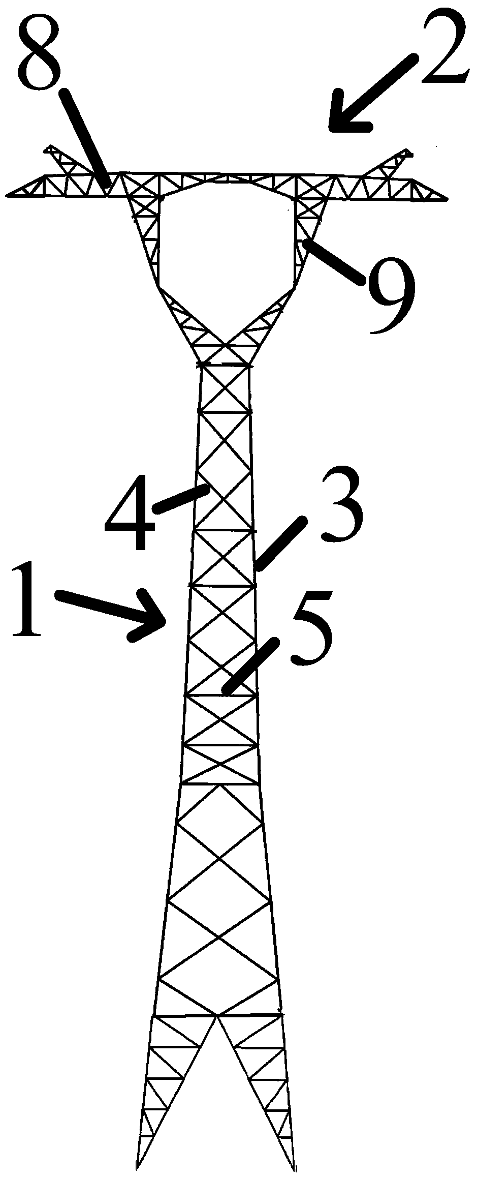
[0049] Such as figure 1 As shown, a weather-resistant steel transmission tower, the transmission tower is provided with a tower body 1 vertically arranged, a tower head 2 arranged horizontally on the upper end of the tower body 1 and a transmission wire arranged on the tower head 2,

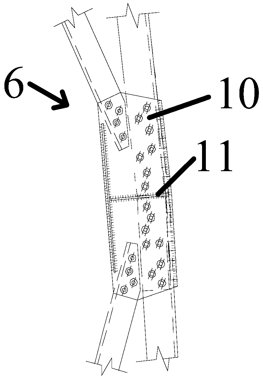
[0050] Such as figure 2 As shown, the tower body 1 is a frame structure formed by staggered connection of angle steel main material 3, angle steel oblique material 4 and angle steel horizontal material 5 vertically arranged with the angle steel main material 3, and the angle steel main material 3 and angle steel oblique The material 4 is connected through the gusset plate assembly 6;

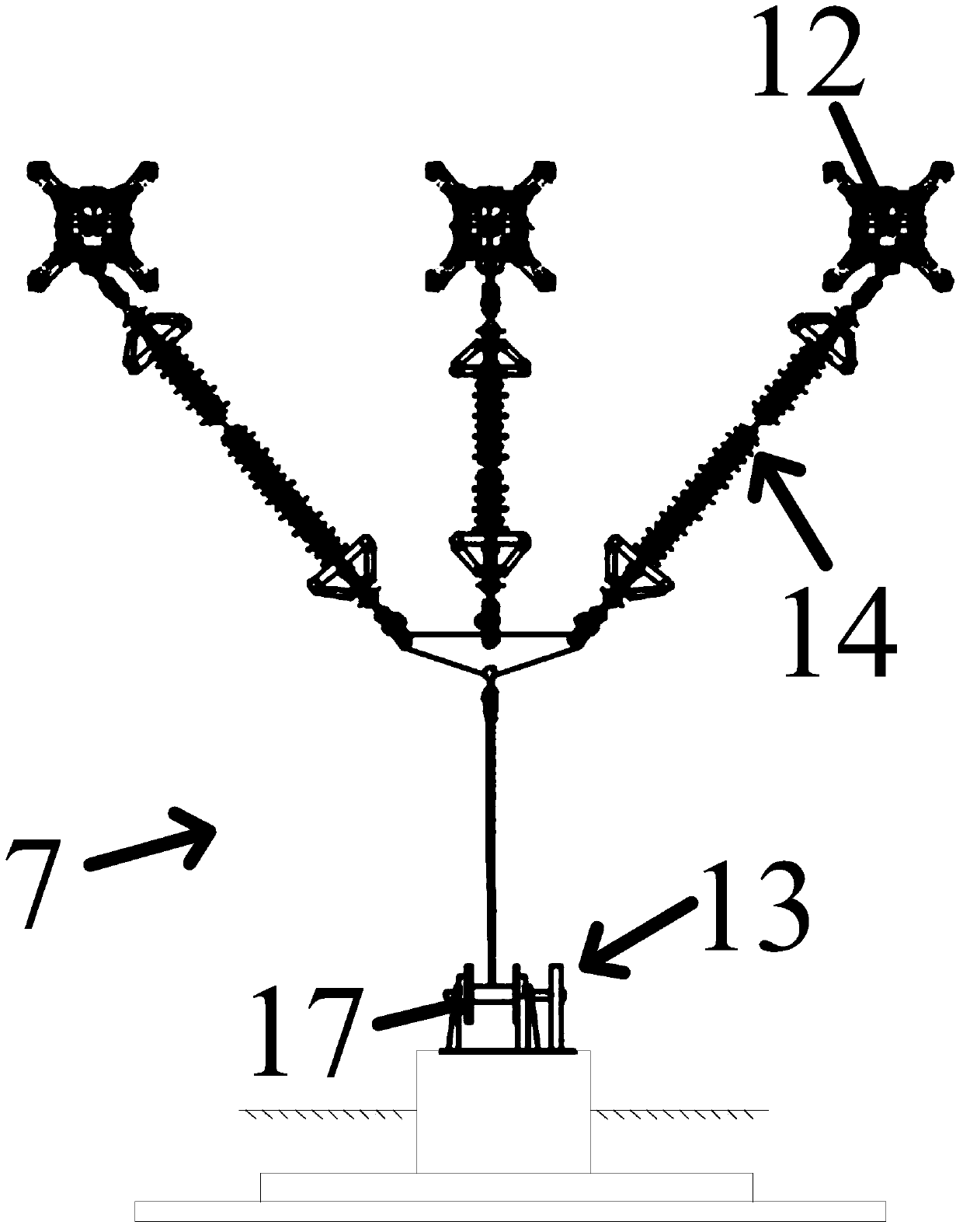
[0051] Such as image 3 As shown, the wire anti-dancing device 7 is provided on the transmission wire.

[0052] Such as figure 1 As shown, the tower head 2 is provided with horizontally arranged cross arms 8, and support vertical beams 9 arranged symmetrically on both sides of the tower body 1 perpendicular to...


PUM


Abstract

The invention provides a transmission tower made of weathering resistant steels. The transmission tower comprises a vertical tower body, a tower head and transmission wires, wherein the tower head is transversely arranged at the upper end of the tower body; the transmission wires are arranged on the tower head; the tower body is a frame structure formed by connecting angle steel main materials, angle steel inclined materials and angle steel transverse materials perpendicular to the angle steel main materials in a staggered manner; the angle steel main materials are connected with the angle steel inclined materials through gusset plate subassemblies; and a wire moving preventing device is arranged on each transmission wire. The transmission tower has the advantages that corrosion resistance of the transmission power is improved, manufacturing cost of the tower is reduced, and the wires of a transmission line are prevented from moving.

Description

technical field [0001] The invention relates to power transmission equipment, in particular to a weather-resistant steel power transmission tower. Background technique [0002] With the rapid development of the grid scale, the demand for transmission towers is also increasing. The operation and maintenance costs of transmission towers caused by steel corrosion are staggering. The atmospheric environment (coastal salt spray and chemical acid rain areas) causes serious corrosion of conventional transmission towers. It can be seen that the corrosion of the iron tower has caused a great waste of transmission tower materials and energy, which seriously affects the safety and reliability of the power grid operation. Therefore, it is necessary to provide a weather-resistant steel transmission tower to prevent corrosion of the transmission tower, resulting in loss of strength and reduction in mechanical properties. [0003] The inventor has found through long-term observation and r...

Claims


Application Information

Patent Timeline
Patent Type & Authority Patents(China)
IPC IPC(8): E04H12/10
CPCE04H12/10
Inventor 李正王旭明韩军科黄耀邢海军胡晓光杨风利张宏杰苏志钢汪长智刘亚多田晓
Owner CHINA ELECTRIC POWER RES INST
Learn More