
Double cleaning and spin-drying device with water level monitoring function for test tubes

A water level monitoring and test tube technology, applied in drying, cleaning hollow objects, drying solid materials, etc., can solve the problems of human health hazards, occupation of long working hours, secondary pollution, etc., to achieve early start time, accurate automatic cleaning, The effect of improving cleaning efficiency

Inactive Publication Date: 2016-03-02
谢文娟
View PDF6 Cites 0 Cited by
  • Summary
  • Abstract
  • Description
  • Claims
  • Application Information

AI Technical Summary

Problems solved by technology

[0003] And in the process of existing manual cleaning, there are following problems: 1. when cleaning, need the staff member to throw out the solution in the test tube with hand, if when operating a large amount of test tubes, repetitive work takes up a large amount of working hours, causes whole cleaning process inefficiencies
[0004] ②Due to the small volume of the test tube, it is easy to pollute the outer surface of the test tube during the process of throwing out the solution, causing secondary pollution and increasing the cleaning workload
[0005] ③During the transfer process, due to the manual operation, human organs such as fingers will come into contact with the sample solution in the test tube, or volatile organic gases enter the human body through the respiratory organs, and the solvent in the test tube solution may be toxic such as toluene and n-hexane. Harmful organic solvents, causing great harm to human health

Method used


Image

  • Double cleaning and spin-drying device with water level monitoring function for test tubes
  • Double cleaning and spin-drying device with water level monitoring function for test tubes

Examples


Embodiment Construction

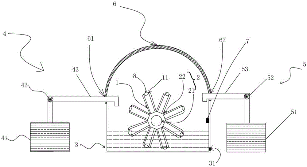
[0025] see figure 1 , which is a structural schematic diagram of a test tube double cleaning and drying device with water level monitoring of the present invention.

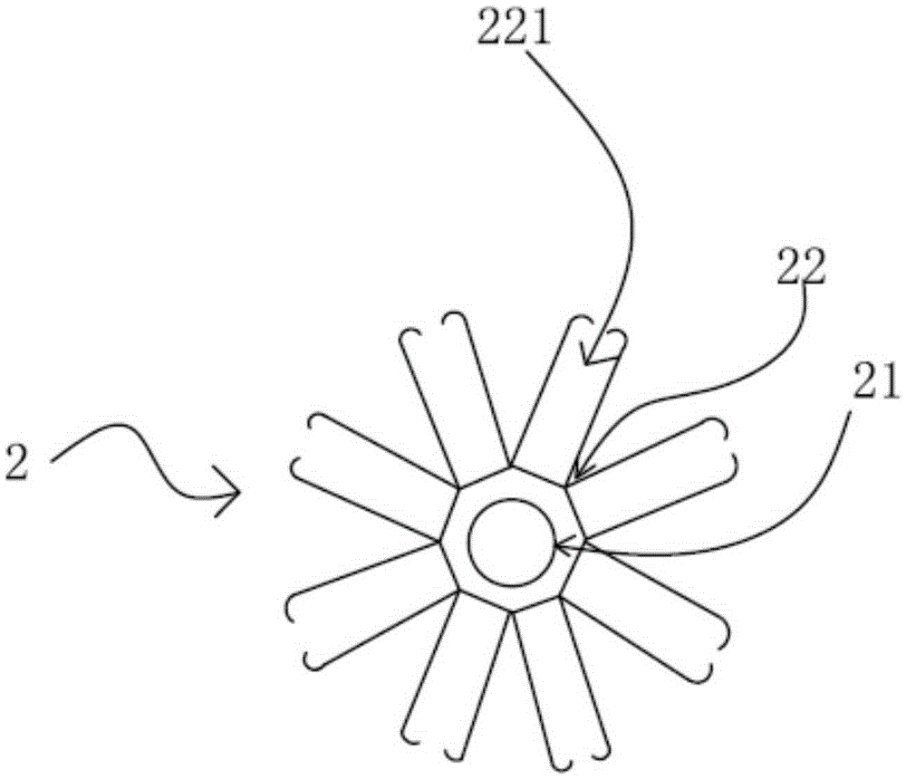
[0026] A test tube double cleaning and drying device with water level monitoring of the present invention comprises a clamping mechanism 1, a rotating mechanism 2, a cleaning tank 3, a cleaning liquid supply mechanism 4, a pure water supply mechanism 5, a sealing cover 6 and a water level detection device7.

[0027] The clamping mechanism 1 is arranged on the rotating mechanism 2 for fixing the test tube 8 in the clamping mechanism 1 .

[0028] The rotating mechanism 2 is used to control the rotation of the clamping mechanism 1 .

[0029] The cleaning tank 3 is arranged below the rotating mechanism 2, and cleaning liquid is stored inside the cleaning tank 3. The rotating mechanism 2 drives the clamping mechanism 1 to rotate, and when the test tube 8 in the clamping mechanism 1 invades into the cleaning solutio...


PUM


Abstract

The invention relates to a double cleaning and spin-drying device with water level monitoring function for test tubes. The double cleaning and spin-drying device comprises a clamping mechanism, a rotating mechanism, a cleaning tank, a cleaning fluid supply mechanism, a purified water supply mechanism, a sealing cover and a water level detector; the clamping mechanism is arranged on the rotating mechanism and used for fixing a test tube therein; the rotating mechanism is used for controlling rotation of the clamping mechanism; the cleaning tank is arranged below the rotating mechanism, and a cleaning fluid is stored within the cleaning tank; the sealing cover is arranged above the clamping mechanism and a rotating mechanism in a covering manner, and the bottom of the sealing cover is fitted with an upper edge of the cleaning tank; a fluid supply opening and a water supply opening are formed in the sealing cover; the cleaning fluid supply mechanism supplies the cleaning fluid to the cleaning tank through the fluid supply opening; the purified water supply mechanism supplies purified water to the cleaning tank through the water supply opening; the water level monitor is arranged on an inner wall of the cleaning tank and used for monitoring a water level, and is capable of controlling the cleaning fluid supply mechanism or the purified water supply mechanism to stop working when the water level reaches a threshold.

Description

technical field [0001] The invention relates to a cleaning device, in particular to a test tube double cleaning and drying device with water level monitoring. Background technique [0002] In the course of experiments or work, test tubes are often used for various chemical experiments. Among them, the test tube is an important tool in the whole detection process, and cleaning the used test tube is an important step in the post-experiment treatment. When a large number of test tubes need to be cleaned, because of the large number, manual cleaning is slow, which will increase the working time for post-test processing. If the efficiency of the sample bottle cleaning step can be improved, the working gap between the previous batch and the next batch can be well connected, and the overall efficiency of the detection work can be improved. [0003] And in the process of existing manual cleaning, there are following problems: 1. when cleaning, need the staff member to throw out th...

Claims


Application Information

Patent Timeline
Patent Type & Authority Applications(China)
IPC IPC(8): B08B9/26B08B9/42B08B13/00F26B5/08
CPCB08B9/26B08B9/426B08B13/00F26B5/08
Inventor 谢文娟
Owner 谢文娟
Learn More