
A fiber array cathode

A cathode and array technology, applied in the field of microwave sources in the field of high-power microwave technology, can solve the problems of non-planting, poor high-temperature ablation resistance, and easy deformation, so as to ensure technical performance, improve high-temperature ablation resistance, The effect of prolonging the working life

Active Publication Date: 2017-05-24
NAT UNIV OF DEFENSE TECH
View PDF4 Cites 0 Cited by
  • Summary
  • Abstract
  • Description
  • Claims
  • Application Information

AI Technical Summary

Problems solved by technology

[0005] The advantage of chemical fiber velvet cathode is that the fluff has good uniformity, so the emission current is uniform, and the disadvantage is that it has poor high temperature ablation resistance, while carbon fiber, glass fiber, and ceramic fiber have good high temperature ablation resistance, but at present, carbon fiber, glass fiber, ceramic fiber The advanced flocking technology is still immature, and it is not possible to plant carbon fiber velvet, glass fiber velvet or ceramic fiber velvet to achieve the uniformity of chemical fiber velvet.
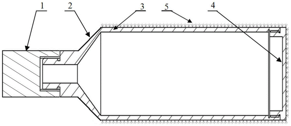
Chinese patent application "A Disc Array Cathode" (Document 3: A Disc Array Cathode [P], Fan Yuwei et al., Invention Patent, Application No.: 201510423394.6) takes advantage of the high temperature ablation resistance of carbon fiber and glass fiber , but the carbon fiber cloth or glass fiber cloth used to make the dielectric disc is soft and easy to deform during the production process, so the produced dielectric disc is often not strictly circular (the dielectric disc with strict circular shape is produced It is very difficult), which has a certain impact on the uniformity of the fiber on the side of the cathode, so it will have a certain impact on the quality of the emitted electron beam, which will eventually be detrimental to improving the overall performance of MILO

Method used


Image

  • A fiber array cathode
  • A fiber array cathode
  • A fiber array cathode

Examples


Embodiment Construction

[0020] The specific embodiments of the present invention will be further described below in conjunction with the accompanying drawings.

[0021] Figure 4 It is a sectional view of the fiber array cathode of the present invention along the central axis, and the cathode is symmetrical around the axis. The fiber array cathode of the present invention is composed of a cathode seat 1, a tapered section 2, a cathode base 3, a porous array ring 4, a "U"-shaped fiber bundle 5, a circumferential gasket 6, and a cathode cap 7. The porous array ring 4, " U"-shaped fiber bundles 5 and circumferential spacers 6 form a fiber bundle circumferential array. The "U"-shaped fiber bundle 5 is generally made of carbon fiber bundles, glass fiber bundles or ceramic fiber bundles, or other materials with low emission threshold and high temperature ablation resistance, and other parts are made of stainless steel materials.

[0022] Its structure and assembly relationship are as follows:

[0023] F...


PUM


Abstract

The invention relates to a fiber array cathode, and belongs to the field of a microwave source in the technical field of high-power microwaves. The fiber array cathode is formed by sleeving fiber bundle circumference arrays composed of porous array circular rings, U-shaped fiber bundles and circumference pads on a cathode substrate, wherein the two ends of each U-shaped fiber bundle are exposed at the side surface of a cathode to form a dense fiber array so as to replace velvet in a conventional cathode, the porous array circular rings have structural support and current conduction effects, and the dense fiber arrays formed by the fiber bundles mainly generate cathode plasma under the effect of a strong electric field and accordingly generate relativistic electron beams. The employed fiber bundles are generally carbon fiber bundles, glass fiber bundles or ceramic fiber bundles, or other materials with low emission thresholds and high temperature ablation resistance. Since the employed fiber bundle materials are better in high temperature ablation resistance than chemical fiber velvet in the conventional cathode, by use of the long-life fiber array cathode with the high temperature ablation resistance, the operation life of a MILO can be greatly prolonged.

Description

technical field [0001] The invention relates to a cathode, in particular to a fiber array cathode, which belongs to the field of microwave sources in the technical field of high-power microwaves. Background technique [0002] Magnetically Insulated Transmission Line Oscillator (MILO) is an important high-power microwave source, and it is one of the hotspots of high-power microwave source research at home and abroad. The cathode is an important part of MILO, and a good cathode design is the prerequisite for MILO to obtain high performance. Traditional MILO generally uses chemical fiber velvet cathodes, because the chemical fiber velvet cathodes are not resistant to high temperature ablation, so their operating life is relatively short. This is the most important problem restricting the long-life operation of MILO. [0003] The traditional compact MILO cathode consists of a cathode seat, a conical section, a lateral cathode, an axial cathode and velvet (Document 1: Fan Yuwei...

Claims


Application Information

Patent Timeline
Patent Type & Authority Patents(China)
IPC IPC(8): H01J23/04H01J25/42
CPCH01J23/04H01J25/42
Inventor 樊玉伟李安昆王晓玉杨汉武张建德李志强
Owner NAT UNIV OF DEFENSE TECH
Learn More