Fiber smoke sensor
A smoke sensor and optical fiber technology, applied in the field of automatic smoke alarm equipment, can solve the problems of high detector structure, inconvenient installation, easy aging, etc., and achieve the effect of reducing interference
- Summary
- Abstract
- Description
- Claims
- Application Information
AI Technical Summary
Problems solved by technology
Method used
Image
Examples
Embodiment 1
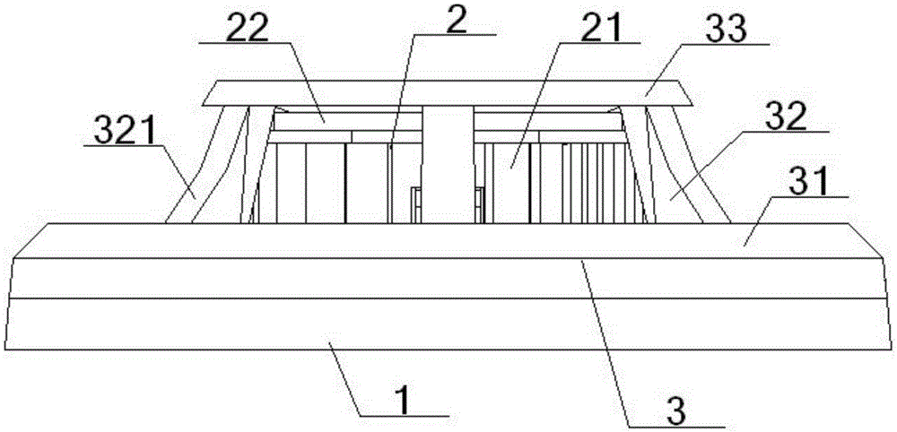
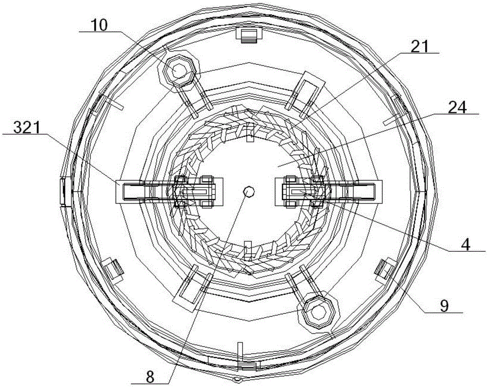
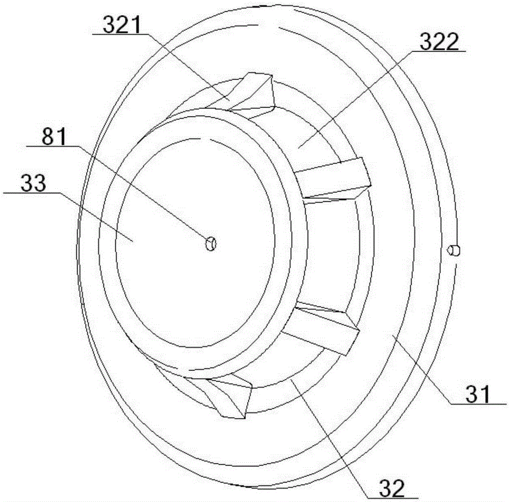
[0063] see figure 1 – Figure 12 , an optical fiber smoke sensor, comprising a bottom case 1, a smoke chamber 2, a mask 3 and an optical fiber fixing device 4, the mask 3 is a concave structure, including a top cover part 31, a middle cover part 32 and a bottom cover part 33, the The periphery of the bottom cover part 33 is connected with the middle part of the top cover part 31 through the middle cover part 32, and the periphery of the top cover part 31 is connected with the periphery of the bottom shell 1, and the bottom shell 1 is provided with a fixing hole 10, and the bottom shell 1 The middle part of the front is connected with the smoke chamber 2, the outside of the smoke chamber 2 is covered in the mask 3, and the inside of the smoke chamber 2 is provided with an optical fiber fixing device 4;
[0064] The optical fiber fixing device 4 includes a left-right symmetrical optical fiber inlet 41 and an optical fiber outlet 42 with the same structure, and the symmetrical p...
Embodiment 2
[0066] Basic content is the same as embodiment 1, the difference is:
[0067] The two sides of the front wide plate 61 are respectively connected with a side plate 63 , and the side plate cavity 64 formed between the two side plates 63 is inlaid with the fiber receiving platform 51 inside. Described side plate 63 comprises front long side plate 631, medium and short side plate 632 and rear long side plate 633, and middle and short side plate 632 is shorter than front long side plate 631, rear long side plate 633, and front long side plate 631, rear long side plate 633 One end of the long side plate 633 is connected to the side of the front wide plate 61 , and the other ends of the front long side plate 631 and the rear long side plate 633 are engaged with the side plate hole 65 opened on the front of the bottom case 1 .
Embodiment 3
[0069] Basic content is the same as embodiment 1, the difference is:
[0070] The smoke chamber 2 includes a smoke inlet portion 21 and a circular chassis portion 22. The smoke inlet portion 21 includes a plurality of smoke inlet pieces 23 uniformly distributed in the same circle along the chassis portion 22, and the smoke inlet pieces 23 are surrounded by a The smoke gathering area 24 is circular, and a smoke inlet passage 25 is formed between adjacent smoke inlet pieces 23; two smoke chamber gaps 26 are opened on the smoke inlet portion 21, and each smoke chamber gap 26 is located on the other side. One fiber-supporting platform 51 inside is correspondingly engaged, and the two smoke chamber gaps 26 are symmetrically arranged with the center of the chassis portion 22 as a symmetrical point. The shape of the smoke-introducing sheet 23 is herringbone, letter-shaped, T-shaped or splayed. The smoke inlet part 21 also includes a pair of fixed feet 27, which are symmetrically arr...
PUM
 Abstract
Description
Claims
Application Information
 - R&D
- Intellectual Property
- Life Sciences
- Materials
- Tech Scout
- Unparalleled Data Quality
- Higher Quality Content
- 60% Fewer Hallucinations
Browse by: Latest US Patents, China's latest patents, Technical Efficacy Thesaurus, Application Domain, Technology Topic, Popular Technical Reports.
© 2025 PatSnap. All rights reserved.Legal|Privacy policy|Modern Slavery Act Transparency Statement|Sitemap|About US| Contact US: help@patsnap.com


