
Inlaying source device used for scintillation crystal detector gain automatic control

A technology of automatic gain control and scintillation crystal, which is applied in the direction of measuring devices, instruments, scientific instruments, etc., can solve the problems of little performance change, low detection efficiency, and difficult production, and achieve simple production process, high light collection efficiency, and detection The effect of improving efficiency

Inactive Publication Date: 2016-02-24
NAT INST OF METROLOGY CHINA +1
View PDF8 Cites 8 Cited by
  • Summary
  • Abstract
  • Description
  • Claims
  • Application Information

AI Technical Summary

Problems solved by technology

[0004] 2) After the photomultiplier tube works for a long time and the aging of the electronic circuit may cause the change of the system gain
[0005] 3) After the external working temperature changes, the luminous efficiency and electronic system gain of NaI or CsI crystals may also change, resulting in a linear change in energy
[0006] 4) The fluctuation of PMT high voltage will also cause the fluctuation of detector gain
[0008] for automatic gain control 241 There are two main ways of Am mosaic source, one is to melt the plastic scintillator with 241 After the Am solution is evenly mixed, the plastic scintillator is solidified to obtain a uniformly distributed mosaic source, but this solution is difficult to manufacture, and it is necessary to ensure that the performance of the plastic scintillator does not change much after melting and curing; another way is to 241 Am is plated on the metal surface, and then the plastic scintillator is bonded to the metal surface to realize the sealing of the radioactive source. This scheme is easy to make but 241 Am's α particle detection solid angle is less than 2π, resulting in low detection efficiency

Method used


Image

  • Inlaying source device used for scintillation crystal detector gain automatic control

Examples


Embodiment Construction

[0022] The technical solutions of the present invention will be described in further detail below with reference to the accompanying drawings and embodiments.

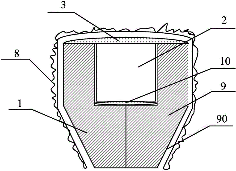
[0023] figure 1 It is a schematic diagram of the mosaic source device used for the automatic control of scintillation crystal detector gain of the present invention. As shown in the figure, the present invention includes: a plastic scintillator cylinder 1 , a plastic scintillator cylinder 2 and an epoxy resin layer 3 .

[0024] Attached to the bottom of the plastic scintillator cylinder is a 241 Am radioactive source 10;. The plastic scintillator cylinder 2 is plugged into the plastic scintillator cylinder 1, and against the 241 Am radiation source 10, thereby forming plastic scintillator 9, plastic scintillator 9 outside has reflective coating 90; 241 The Am radiation source 10 is sealed inside the plastic scintillator 9 .

[0025] 241 The Am radioactive source is specifically passed by the 241 The Am radioactiv...


PUM


Abstract

The invention relates to an inlaying source device used for scintillation crystal detector gain automatic control. The inlaying source device comprises a plastic scintillator barrel, a plastic scintillator cylinder and an epoxy resin layer. A 241Am radioactive source is adhered on the bottom part of the plastic scintillator barrel. The plastic scintillator cylinder is plugged in the plastic scintillator barrel and abutted against the 241Am radioactive source so that a plastic scintillator is formed. A reflective coating layer is arranged at the external side of the plastic scintillator. The epoxy resin layer is connected on the top part of the plastic scintillator cylinder in a sealing way and used for sealing the 241Am radioactive source in the plastic scintillator. According to the inlaying source device used for scintillation crystal detector gain automatic control, the manufacturing process of the 241Am radioactive source is simple and easy to realize; and light collection efficiency is high so that signal-to-noise ratio is effectively enhanced and detection efficiency of alpha particles is greatly enhanced.

Description

technical field [0001] The invention relates to a mosaic source device, in particular to a mosaic source device used for automatic gain control of a scintillation crystal detector. Background technique [0002] The energy response of commonly used NaI or CsI crystal detectors may be affected by environmental magnetic field, temperature and other factors. The relevant effects are detailed as follows: [0003] 1) As the geomagnetic field changes, the gain of the photomultiplier tube (PMT) of the scintillation detector will be affected by the slowly changing geomagnetic field. [0004] 2) After the photomultiplier tube works for a long time and the aging of the electronic circuit may cause the change of the system gain. [0005] 3) After the external working temperature changes, the luminous efficiency and electronic system gain of NaI or CsI crystals may also change, resulting in a linear change in energy. [0006] 4) The fluctuation of PMT high voltage will also cause the f...

Claims


Application Information

Patent Timeline
Patent Type & Authority Applications(China)
IPC IPC(8): G01T1/203
CPCG01T1/203
Inventor 梁珺成李正伟刘聪展阎博刘皓然
Owner NAT INST OF METROLOGY CHINA
Learn More