A marking vehicle for three-lane roads

A marking car and three-lane technology, which is applied in the field of construction machinery, can solve problems such as inapplicability, and achieve the effects of convenient control, simple operation and wide application range

Active Publication Date: 2017-05-24
广州市公路实业发展有限公司
View PDF4 Cites 2 Cited by
  • Summary
  • Abstract
  • Description
  • Claims
  • Application Information

AI Technical Summary

Problems solved by technology

[0002] Generally speaking, after the construction of the main part of the highway, it is necessary to divide the lanes on the highway. Among the various lane divisions, the planning of the single white line is the most difficult, because when marking the lines, people not only need to ensure The length of each single white line in the length direction is constant and the distance between two adjacent single white lines is constant. In the width direction of the road surface, the width of each lane is equal and the start and end ends of the single white line are flush. Although some construction machinery can do this, when the condition of the road to be marked changes, the width of the lane will often change. For example, the three-lane road to be marked is compared to the original road. When the lane width of the highway marked by machinery is increased by X width, the single white line between its first lane and second lane is equivalent to shifting X distance to the side, and the single white line between its second lane and third lane The white line is equivalent to a 2X distance to the side, and the single white line of the same lane and the opposite lane needs to be adjusted in this way, and traditional construction machinery is often not suitable for this because it is difficult to adapt to the change of lane width. lane marking job

Method used


Image

  • A marking vehicle for three-lane roads
  • A marking vehicle for three-lane roads
  • A marking vehicle for three-lane roads

Examples


Embodiment Construction

[0026] In order to make the technical means, creative features, goals and effects achieved by the present invention easy to understand, the present invention will be further elaborated below.

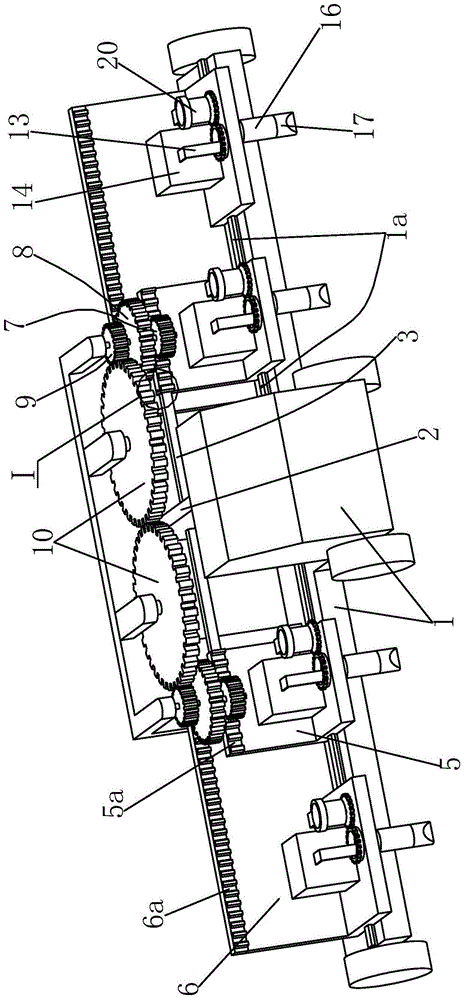
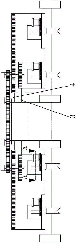
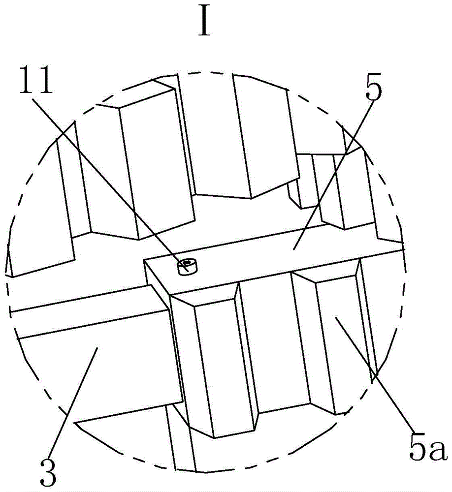
[0027] Such as Figure 1 to Figure 5 As shown, a marking vehicle for three-lane roads mainly includes a car body 1, a center frame 2 is arranged at the center of the car body 1, and the left and right ends of the center frame 2 are sequentially arranged from bottom to top. A No. 1 sliding frame 3 and a No. 2 sliding frame 4 are horizontally installed, and the No. 1 sliding frame 3 and No. 2 sliding frame 4 are respectively slidingly connected to a No. 1 carrier frame 5 at the end away from the center frame 2 in a one-to-one correspondence. , No. 2 carrier frame 6, the car body 1 has a slide rail 1a that is slidably installed with two No. 1 carrier frames 5 and two No. 2 carrier frames 6.

[0028] A No. 1 rack 5a is installed on the top of the No. 1 carrier 5, and No. 2 rack 6a is insta...


PUM


Abstract

The invention relates to a marking vehicle used for a three-lane road. The marking vehicle mainly comprises a vehicle body. A central frame is arranged on the vehicle body. A No.1 sliding holder and a No.2 sliding holder are installed on the central frame. The No.1 sliding holder and the No.2 sliding holder are in sliding connection with a No.1 bearing holder and a No.2 bearing holder respectively. A No.1 rack is installed on the No.1 bearing holder and a No.2 rack is installed on the No.2 bearing holder. The No.1 rack is engaged to a No.1 gear. The No.1 gear is connected with a No.2 gear and transmission gears. The No.2 gear is engaged to the No.2 rack. Two idle gears are arranged between the two transmission gears. Plugging covers are arranged at the lower end of the No.1 bearing holder and the lower end of the No.2 bearing holder respectively. An opening is arranged beside each plugging cover. The upper end of each plugging cover is pressed against a bar-shaped pipe. The bar-shaped pipe is connected with a raw material storage box. Annular teeth are arranged at the circumferential outer end of each plugging cover. The annular teeth are engaged to an auxiliary gear. The marking vehicle has functions of ensuring marking length and marking interval constant and marking of roads with different lane widths.

Description

technical field [0001] The invention relates to the field of engineering machinery, in particular to a marking vehicle for three-lane roads. Background technique [0002] Generally speaking, after the construction of the main part of the highway, it is necessary to divide the lanes on the highway. Among the various lane divisions, the planning of the single white line is the most difficult, because when marking the lines, people not only need to ensure The length of each single white line in the length direction is constant and the distance between two adjacent single white lines is constant. In the width direction of the road surface, the width of each lane is equal and the start and end ends of the single white line are flush. Although some construction machinery can do this, when the condition of the road to be marked changes, the width of the lane will often change. For example, the three-lane road to be marked is compared to the original road. When the lane width of th...

Claims


Application Information

Patent Timeline
Patent Type & Authority Patents(China)
IPC IPC(8): E01C23/22
Inventor 罗小雄邓庆光周耀坤
Owner 广州市公路实业发展有限公司
Why Eureka
Try Eureka