Reel

A reel and reel shaft technology, applied in the direction of the hoisting device, the spring mechanism, etc., can solve the problem that the braking and parking device is prone to failure, cannot be used as a stressed wire rope or an insurance rope for a hanging basket, and the end wire rope is damaged and broken And other issues

Pending Publication Date: 2016-02-24
吴超然
View PDF6 Cites 6 Cited by
  • Summary
  • Abstract
  • Description
  • Claims
  • Application Information

AI Technical Summary

Problems solved by technology

Since the wire rope wound on the reel is not allowed to be fully rotated and extended out of the reel, the reel is subjected to a large torque when the wire rope hoists heavy objects and hovers in the air, and the brake must be used to ensure that the heavy objects Hovering in the air, so the hoist cannot bear a large load, especially for a long time to hang heavy objects in the air, especially because the braking and parking device of the hoist is prone to failure, so the existing regulations proh...

Method used


Image

  • Reel
  • Reel
  • Reel

Examples


Embodiment Construction

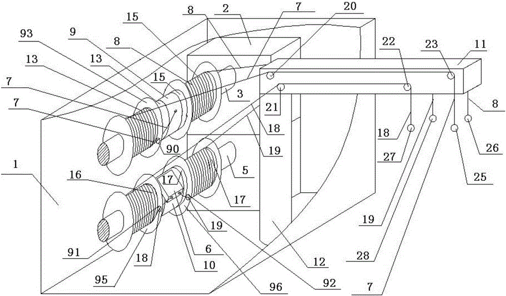
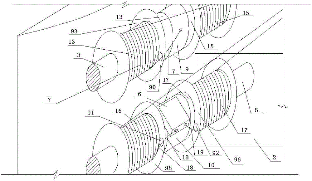
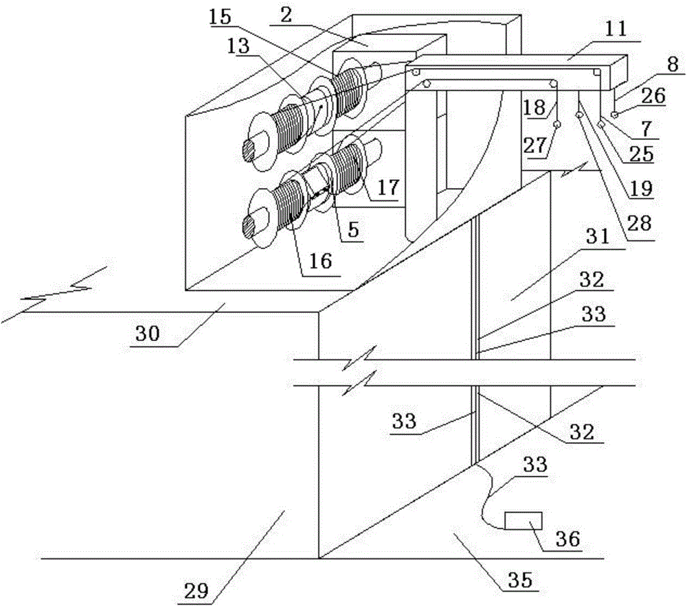
[0088] Such as figure 1 as shown, figure 1 It is a schematic oblique view of the first embodiment of the multifunctional rope-releasing device used by the reel of the present application. The multifunctional rope-releasing device includes a housing 1, a motor 2, a rotating shaft 3, a rotating shaft 5, a descending device 6, a pull rope 7, a pull rope 8, a connecting end support 9, a connecting end support 10, Cantilever 11, column 12, above-mentioned motor 2, rotating shaft 3, rotating shaft 5, descender 6, stay rope 7, stay rope 8, connection end support 9, connection end support 10, and column 12 are arranged in the shell In the body, the motor 2 is connected to the rotating shaft 3 and the rotating shaft 5 to drive the rotating shaft 3 and the rotating shaft 5 to rotate. Fixed connection, the above-mentioned connecting end support 9 is sleeved on the outer periphery of the rotating shaft 3 and can rotate in one direction around the rotating shaft 3, the above-mentioned co...


PUM


Abstract

The invention provides a reel. Multiple rope blocking plates are arranged on the reel and a reel shaft of the reel. At least one rope blocking plate is provided with a hole where a steel wire rope can penetrate. The reel or the reel shaft of the reel is provided with a connection end support of the steel wire ropes. The steel wire rope connection end support is only used for fixing or winding multiple circles of end steel wire ropes and no steel wire rope is wound around and stacked on the multiple circles of end steel wire ropes.

Description

technical field [0001] The application belongs to a reel applied to lifting equipment. Background technique [0002] The main function of the existing lifting equipment such as the hoist is to lift and pull the heavy object to go up or down. If it hovers in the air, it depends on the braking device of the reel to stop. The existing regulations require that the wire rope of the hoist cannot be pulled completely. It must be ensured that the steel wire rope coiled on the drum is kept for at least 3 turns to ensure the safety of the stress-bearing end. If all the steel wire rope coiled on the drum is released, the steel wire rope will be fixed and connected to the pressure plate on the drum through the pressure plate. And the anchor bolts are very vulnerable to the radial tension, and they are peeled off the reel one by one to cause danger. It is precisely because of the above reasons that the steel wire rope extending from the fixed end of the wire rope is at least wound on the...

Claims


Application Information

Patent Timeline
IPC IPC(8): B66D1/08B66D1/12B66D1/30B66D1/28B66D5/08
Inventor 吴超然
Owner 吴超然
Why Eureka
Try Eureka