
Dolly structure

A trolley and structure technology, applied in the direction of trolleys, motor vehicles, trolley accessories, etc., can solve the problems of change, braking, slipping and braking force, etc., to reduce the force and realize the effect of operating force

Inactive Publication Date: 2016-02-17
NANSIN CO LTD
View PDF8 Cites 4 Cited by
  • Summary
  • Abstract
  • Description
  • Claims
  • Application Information

AI Technical Summary

Problems solved by technology

[0002] In the case of simultaneously braking the left and right wheels of the trolley, there is a risk of brake slippage or changes in braking force due to wheel wear in the braking method in which the brake shoes are pressed against the contact surface of the wheels.

Method used


Image

  • Dolly structure
  • Dolly structure
  • Dolly structure

Examples


Embodiment 1

[0042] [Trolley]

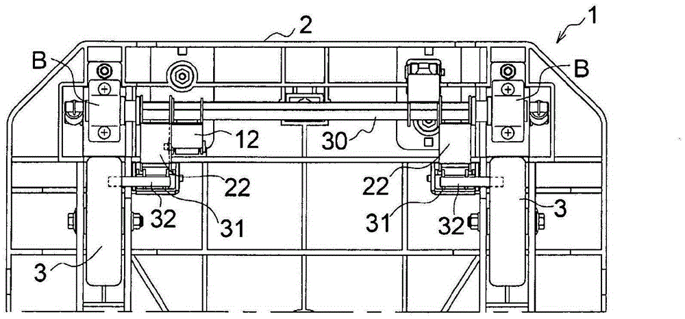
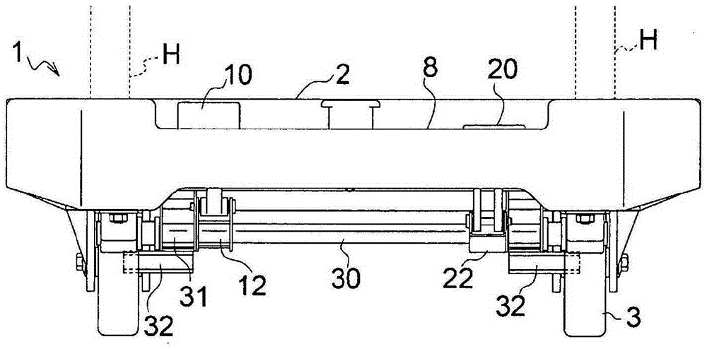
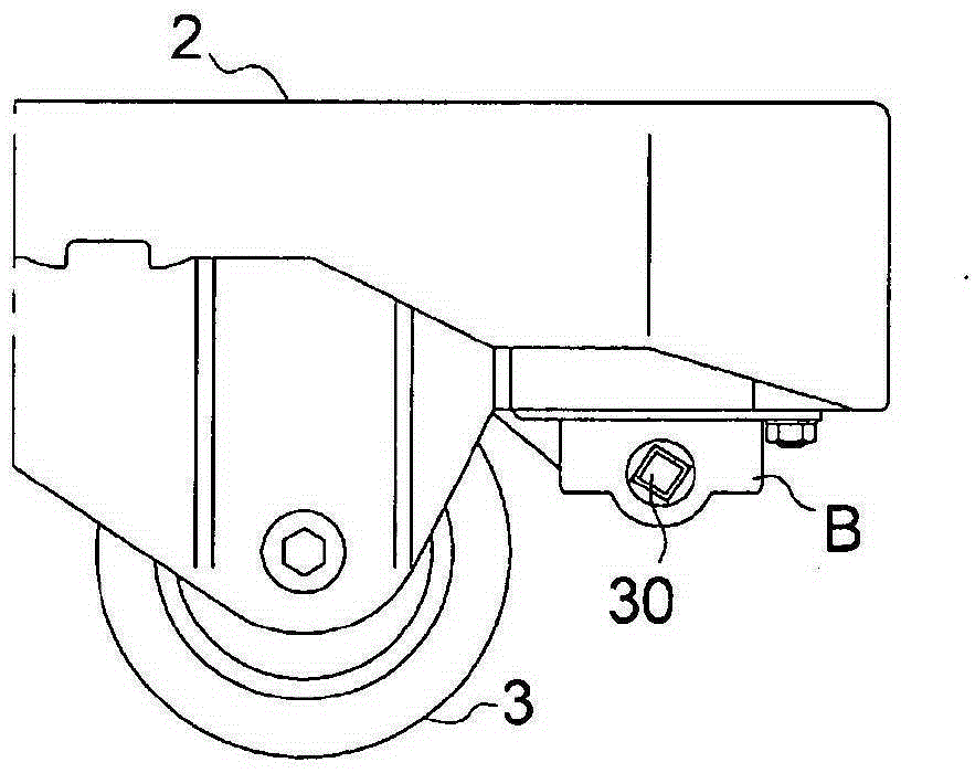
[0043] Such as figure 1 with figure 2 As shown, the trolley 1 is composed of a chassis 2, a handle (not shown), a pair of left and right wheels 3, and a braking mechanism. The front and rear ends of the chassis 2 are chamfered, and its upper surface becomes a loading surface. The handle is erected near one side of the chassis 2, and the left and right pair of wheels 3 are arranged at the front and rear of the bottom of the chassis 2, and the brake mechanism brakes the wheels 3 on the rear wheel side.

[0044] The wheel 3 has a small-diameter concave portion concentric with the outer circumference, and a gear-shaped internal tooth portion 4 formed of continuous unevenness is formed on the inner peripheral surface of the concave portion.

[0045] Regarding the brake operation, a push-down type brake release pedal 10 and a brake pedal 20 are arranged side by side in the concave portion 8 provided in the space between a pair of legs (H) that are A pair of le...

Embodiment 2

[0083] Figure 9 ~ Figure 11 The shown trolley 1 shows different embodiments as follows: a structure in which a detachable back panel 50 is provided on the handle H, and a structure that is foldable at three positions of the frontmost part and the left and right sides of the chassis 2 via pins 41 Collapsible scatter arrest sheet 40 .

[0084] That is, the scattering prevention sheet 40 is configured to be folded so as to be flush with the upper surface of the chassis 2 when folded (refer to Figure 12 (b), Figure 13 (b) dotted line), and when unfolded, it is unfolded in a manner to stand approximately vertically with respect to the upper surface of the chassis 2 (refer to Figure 12 (a), Figure 13 (a) ~ (b)).

[0085] That is, if Figure 13 As shown in (c), the pin 41 is hooked to the side of the top plate so as not to fall out, and the drop preventing sheet 40 is accommodated in the recessed storage portion 42 so that the outer surface of the folded sheet is flush with...


PUM


Abstract

The present invention relates to an improvement of a wheel structure for simultaneously applying or releasing braking on right and left wheels of a dolly or the like. An interlock shaft (30) pivotally connected to the deck (2) of a dolly is rotated by using a locking link piece (21) connected to a braking pedal (20), a pair of right and left cam arms (22, 22) and releasing link pieces (12) are fixed to the interlock shaft (30) in a synchronously operable manner, and braking arms (31) having a cam surface (33) are caused to pivot with rotation of the respective cam arms (22) so as to cause wheel locking sections (32) of the braking arms (31) to engage with or disengage from internal tooth parts of internal tooth sections (4) formed on the inner side of wheels (3) in order to apply or release braking. In addition, releasing link pieces (11), which are pivotally connected to the releasing link pieces and are in a disengaged state, are caused to engage with protrusion pieces (6) formed on the deck (2) with rotation of the releasing link pieces (12) in order to lock the braking state, and the engagement of the releasing link pieces (11) with the deck (2) is released with lowering of a releasing guide section (16) of a breaking releasing pedal (10).

Description

technical field [0001] The present invention relates to an improvement of a bogie structure capable of simultaneously braking and releasing the brakes on the left and right wheels of the bogie. Background technique [0002] When the left and right wheels of the trolley are braked at the same time, there is a risk of brake slippage or changes in braking force due to wheel wear in a braking method in which the brake shoe presses the contact surface of the wheel. [0003] Therefore, the inventor of the present invention proposes the following method, that is, Japanese Patent Application Laid-Open No. 2011-16407, which uses a pair of brake levers to operate the brake and brake release, and Japanese Patent Application No. Like the braking device of a trolley in Japanese Patent Laid-Open No. 2010-163056, the method of locking the groove portion provided on the inner periphery of the wheel portion of the wheel can obtain the following corresponding effects: no brake slip occurs, an...

Claims


Application Information

Patent Timeline
Patent Type & Authority Applications(China)
IPC IPC(8): B62B5/04
CPCB62B5/0433B62B5/0461
Inventor 斋藤彰则成田祐二白木龙彦北侑也
Owner NANSIN CO LTD
Learn More