Connector and LED lamp bar applying connector

A technology of LED strips and connectors

Active Publication Date: 2016-02-17
TPV DISPLAY TECH (XIAMEN) CO LTD
View PDF6 Cites 4 Cited by
  • Summary
  • Abstract
  • Description
  • Claims
  • Application Information

AI Technical Summary

Problems solved by technology

Using the above method, each row of light bars connects two wires 031 and 032 from the outer end of the second LED light bar 012 to the positive and negative poles of the power supply. The reflector usually needs to use adhesive tape 04 to fix the wire, which is not only difficult to construct, requires high welding technology, labor and time, and low production efficiency, but also uses a large number of connectors and poor electrical conductivity, which is easy to affect the light bar. Luminescence stability

Method used


Image

  • Connector and LED lamp bar applying connector
  • Connector and LED lamp bar applying connector
  • Connector and LED lamp bar applying connector

Examples


Embodiment Construction

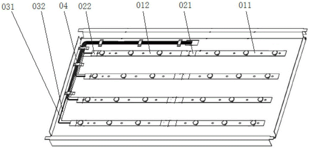
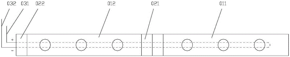
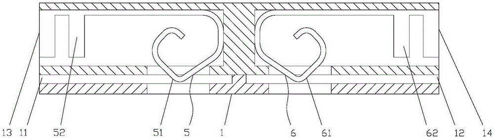
[0027] like Figure 3-4 As shown in one, the connector of the present invention includes a housing 1, and the housing 1 is provided with two light bar interfaces 11, 12 and two wire interfaces 13, 14, and the two light bar interfaces 11, 12 are used for It is connected with two LED light bars 2, the two wire interfaces 13, 14 are used to connect with two wires 3, and the housing 1 is provided with a male terminal 4 and two female terminals 5, 6, the male terminal 4 The two ends are respectively provided with a first male contact 41 and a second male contact 42, and one end of the two female terminals 5, 6 is respectively provided with a first female contact 51 and a second female contact 61, the The first male contact 41 and the first female contact 51, the second male contact 42 and the second female contact 61 are respectively arranged in the two light bar interfaces 11, 12, and the two female terminals 5, 6 The other end is respectively provided with two wrapping pins 52, ...


PUM


Abstract

The invention relates to the technical field of packaging, and particularly relates to a connector and an LED lamp bar applying the connector. The connector comprises a shell which is provided with two lamp bar interfaces and two conductive wire interfaces. The two lamp bar interfaces are used for being connected with two LED lamp bars. The two conductive wire interfaces are used for being connected with two conductive wires. The shell is internally provided with a male terminal and two female terminals. The two ends of the male terminal are respectively provided with a male contact and a second male contact. One end of the two female terminals is respectively provided with a first female contact and a second female contact. The first male contact and the first female contact, and the second male contact and the second female contact are respectively arranged in the two lamp bar interfaces. The other end of the two female terminals is respectively provided with two wire packaging pins which are respectively arranged in the two conductive wire interfaces. The LED lamp bar applies the connector. One end of the LED lamp bar is provided with positive electrode bare copper and negative electrode bare copper. The positive electrode bare copper and the negative electrode bare copper are respectively connected with the male contact and the female contact in one lamp bar interface.

Description

technical field [0001] The invention relates to the technical field of connectors, in particular to a connector and an LED light bar using the connector. Background technique [0002] The development direction of the current LCD TV is that the size is getting bigger and bigger, but due to the limitations of production equipment and technology, it is impossible to make a single LED light bar very long. Usually, it is set at the end of the LED light bar for interconnection or connection. Connect the terminals of the power supply, and use welding to connect the terminals of the LED light strips to each other or to the power cord, so that the two light strips can be spliced ​​together to meet the length requirement. The use of the existing SMT chip welding and then connecting method not only increases the cost of man-hours, but also requires the materials of the parts to be welded to have high temperature resistance, which leads to an increase in material costs. [0003] The sc...

Claims


Application Information

Patent Timeline
Patent Type & Authority Applications(China)
IPC IPC(8): H01R13/02H01R13/50F21S4/00F21Y103/00F21Y115/10
CPCH01R13/02H01R13/50H01R2201/18
Inventor 张振国郭建阳
Owner TPV DISPLAY TECH (XIAMEN) CO LTD
Why Eureka
Try Eureka