
Superplastic forming mold design method based on finite element technique with consideration of thermal expansion

A superplastic forming and mold design technology, applied in the field of mechanical processing and forming simulation, can solve the problems of large deformation, not fully considering the forming error of parts, multi-layer structure, etc., and achieve the effect of improving the forming accuracy

Active Publication Date: 2016-02-17
BEIHANG UNIV
View PDF2 Cites 17 Cited by
  • Summary
  • Abstract
  • Description
  • Claims
  • Application Information

AI Technical Summary

Problems solved by technology

This method relies too much on manual experience, and does not fully consider the part forming error caused by the difference in thermal expansion properties of the mold material and the part material; moreover, superplastic formed parts generally have the characteristics of complex three-dimensional structure, large deformation and multi-layer structure, and the overall scaling The proportion is difficult to meet the different changes of different parts of the actual part during forming, resulting in the difference between the final formed part size and the designed part size

Method used


Image

  • Superplastic forming mold design method based on finite element technique with consideration of thermal expansion
  • Superplastic forming mold design method based on finite element technique with consideration of thermal expansion
  • Superplastic forming mold design method based on finite element technique with consideration of thermal expansion

Examples


Embodiment Construction

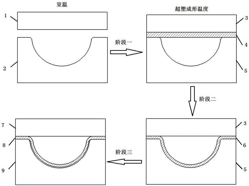
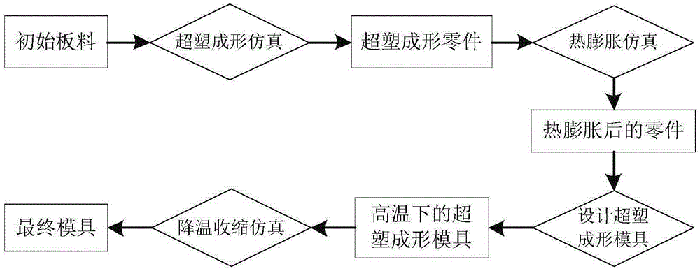
[0030] See figure 1 — image 3 , which will be combined below figure 2 The schematic flow chart of the superplastic forming die design method further explains the design method of a superplastic forming die based on finite element technology considering thermal expansion in this patent application. It includes the following steps:

[0031] Step 1) Carry out the superplastic forming simulation in the finite element simulation software, and calculate and obtain the superplastic forming part.

[0032] Step 2) Using the thermal expansion properties of the part material, the thermal expansion simulation of the superplastic formed part obtained in step 1) is performed separately.

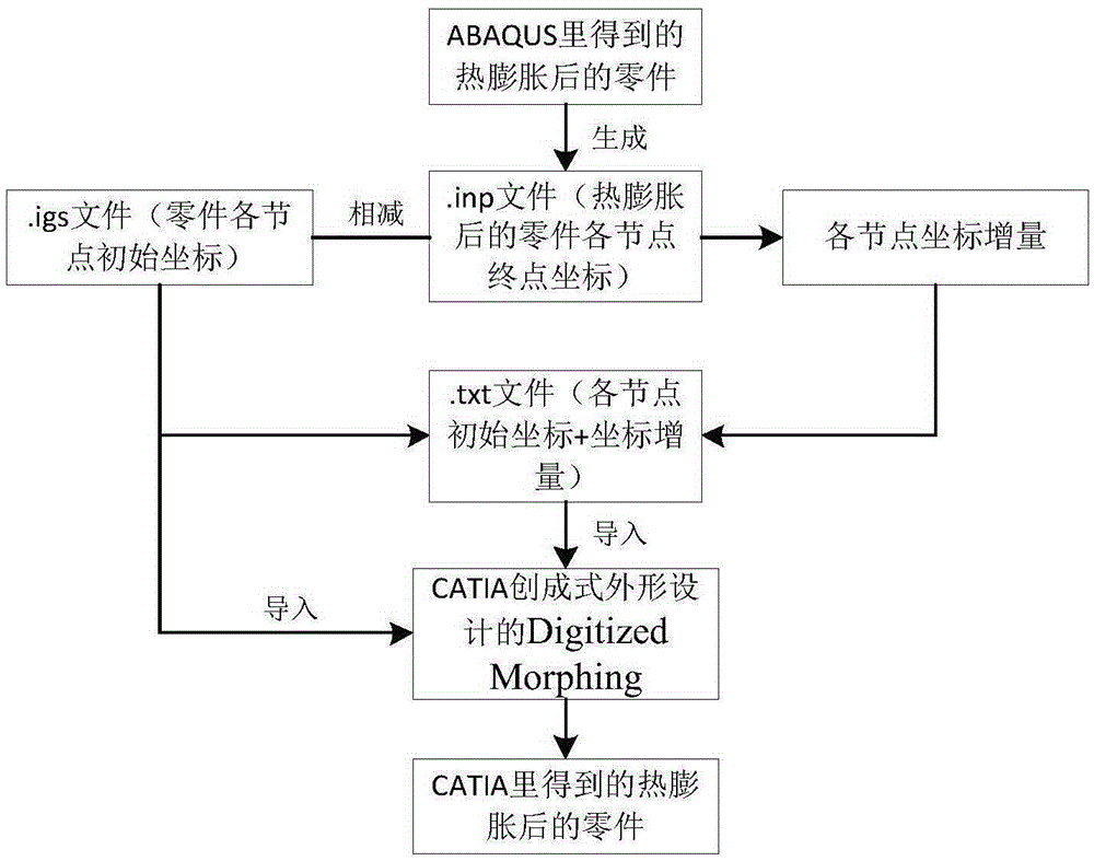
[0033] Step 3) Export the outer contour of the thermally expanded part obtained in step 2), and design the mold surface of the superplastic forming mold and the corresponding three-dimensional overall model of the mold according to the derived result in the three-dimensional modeling software.

[0034...


PUM


Abstract

The invention discloses a superplastic forming mold design method based on a finite element technique with consideration of thermal expansion. The superplastic forming mold design method comprises the following four main steps: I, performing superplastic forming simulation in finite simulation software, and calculating so as to obtain a superplastic formed component; II, by utilizing the thermal expansion property of a component material, performing thermal expansion simulation independently on the superplastic formed component obtained in the step I; III, leading out the outline of the component after thermal expansion in the step II, and according to the leading result, designing a surface and a corresponding three-dimensional overall model of the superplastic forming mold in three-dimensional modeling software; and IV, by utilizing the thermal expansion property of the mold material, performing cooling shrinkage simulation on the superplastic forming mold obtained in the step III at high temperature in the finite simulation software, thereby obtaining a final mold. By adopting the superplastic forming mold design method, forming precision of the superplastic formed component is greatly improved, and direct economic benefits are brought to mold design methods and component manufacturing.

Description

technical field [0001] The invention relates to a design method of a superplastic forming mold considering thermal expansion based on finite element technology, which is applicable to the mold design of various superplastic forming parts, and belongs to the technical field of mechanical processing and forming simulation. technical background [0002] Some materials will undergo superplasticity under certain temperature, strain rate and tissue conditions, that is, their elongation can reach hundreds to thousands of percent, and the forming under such conditions is called superplastic forming. Superplastic forming is especially suitable for forming complex parts with large deformation, and its deformation resistance is small, the residual stress of the part is small, and the springback is small. However, the deformation mechanism of superplastic forming is complex, involving highly nonlinear material nonlinearity, geometric nonlinearity and complex boundary conditions, and the...

Claims


Application Information

Patent Timeline
Patent Type & Authority Applications(China)
IPC IPC(8): G06F17/50G06T17/00
Inventor 李小强郭贵强李东升黄烜昭王珏朱丽
Owner BEIHANG UNIV
Learn More