
Manufacturing method of combined ball clack for high-pressure double-valve-seat track ball valve

A manufacturing method and double valve seat technology, applied in the direction of valve devices, cocks including cut-off devices, engine components, etc., can solve problems such as stuck combination balls, valves cannot be opened, and material creep, etc., to solve dirt deposition, start-up, etc. The effect of fast closing speed and convenient operation

Inactive Publication Date: 2016-02-17
ZHEJIANG PETROCHEMICAL VALVE CO LTD
View PDF0 Cites 3 Cited by
  • Summary
  • Abstract
  • Description
  • Claims
  • Application Information

AI Technical Summary

Problems solved by technology

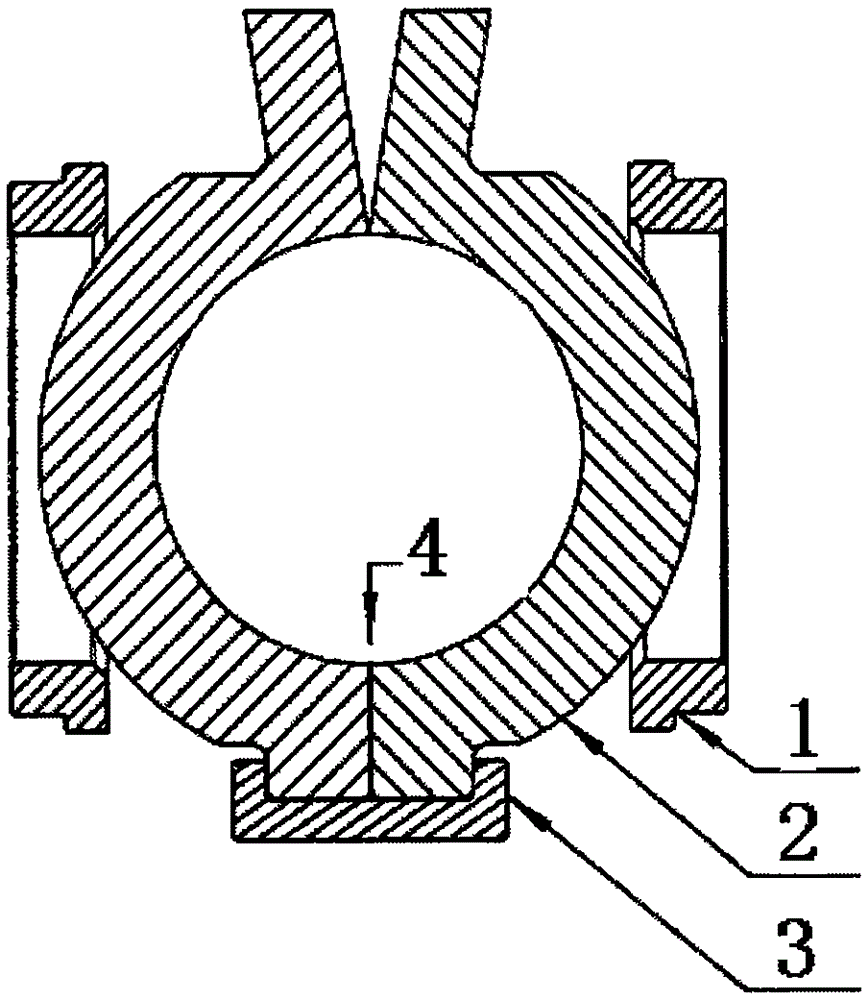
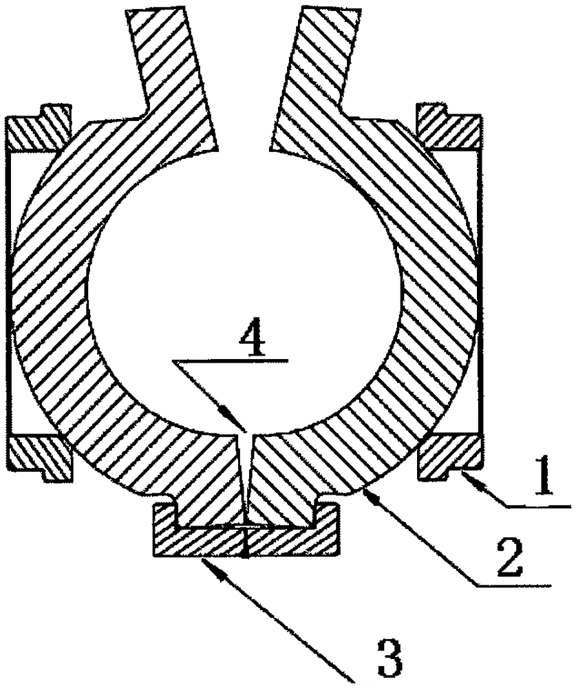
[0003] 1. When the valve is in the open state, the combination sphere is closed, and the two ball petals are in surface-to-surface contact (see figure 1 ); when the valve is in the closed state, the combined sphere is stretched by the valve stem wedge, at this time, the upper parts of the two ball petals of the combined sphere are open, the lower end is line-to-line contact, and the lower end is a V-shaped groove ( See figure 2 ), since the lower ends of the two ball petals have been positioned by the bushing, the mechanical wedging force of the valve stem is transmitted to the line contact at the lower end of the ball petals, and at the same time, the pressure of the medium is also transmitted to the line contact on the ball petals, because The contact surface between the wire and the wire is small, and the strength and specific pressure are not enough, which will inevitably cause the material to creep and cause the valve to not seal tightly
[0004] 2. The double-seat orbital ball valve has very high requirements on the concentricity between the center line of the ball seal and the center line of the valve seat. When the line contact of the two ball discs produces peristalsis, its center will deviate from the center of the valve seat, resulting in the valve not closing tightly.
[0005] 3. When the valve is in the closed state, the upper parts of the two ball valves are open, and the lower ends are V-shaped grooves, and dirt is most likely to deposit dirt in the grooves (see figure 2 ), slight dirt deposits or coking, directly stuck the combined sphere to close normally, resulting in the valve not being able to open

Method used


Image

  • Manufacturing method of combined ball clack for high-pressure double-valve-seat track ball valve
  • Manufacturing method of combined ball clack for high-pressure double-valve-seat track ball valve
  • Manufacturing method of combined ball clack for high-pressure double-valve-seat track ball valve

Examples


Embodiment Construction

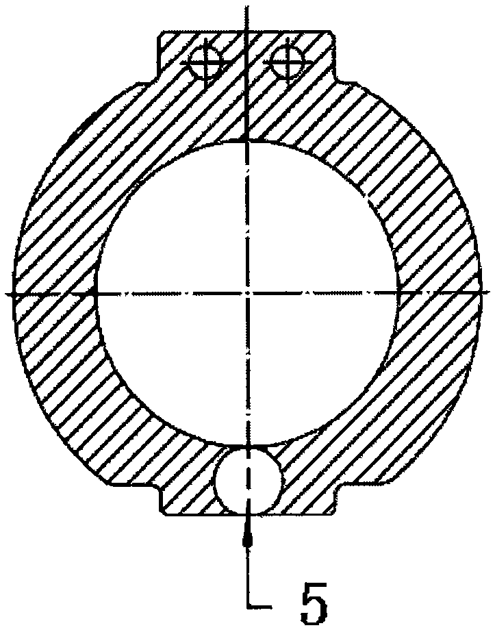
[0016] As shown in the figure, the present invention includes a valve seat 1, a ball valve 2, a shaft sleeve 3, a central joint 4, a circular through hole 5, and a roller 6. The valve cavity of the ball valve is equipped with two valve seats 1 and a ball. The ball is composed of two ball petals 2. The bottom end of the ball is equipped with a shaft sleeve 3. The upper part of the ball is equipped with a combined type brace mechanism. The mechanism supports the opening and closing activities of the two ball petals. This product makes improvements to the sphere, such as image 3 , Figure 4 , Figure 5 , Figure 6 As shown: firstly, a cylindrical through hole is processed at the lower end of the central axis of the entire valve sphere; secondly, the sphere is symmetrically divided into left and right two ball petals 2; again, a roller 6 is processed according to the diameter of the cylindrical through hole 5 ; Then the roller 6 is put into the cylindrical through hole betwee...


PUM


Abstract

The invention provides a manufacturing method of a combined ball clack for a high-pressure double-valve-seat track ball valve. Ball clack bodies and a rolling shaft are of a matched structure, a gap is formed in the center connection position, and normal movement of the combined ball clack is guaranteed. According to the manufacturing method, firstly a cylindrical through hole is machined in the lower end of a center shaft of a whole valve ball body; secondly, the ball body is symmetrically divided into the left ball clack body and the right ball clack body; thirdly, the rolling shaft is machined according to the diameter of the cylindrical through hole; fourthly, the rolling shaft is put into the cylindrical through hole between the two ball clack bodies; and fifthly, the combined ball clack is formed. The combined ball clack is flexible to open and close, high in opening / closing speed and convenient to operate, and meanwhile the problem of dirt deposition at the center connection position of the ball clack is solved.

Description

Technical field: [0001] The invention relates to a method for manufacturing a valve ball disc, in particular to a method for manufacturing a combined ball disc of a high-pressure double-seat orbital ball valve. The combined ball disc is used in high temperature and high pressure, especially harsh working conditions, to ensure bidirectional sealing of the double valve seat Background technique: [0002] Double-seat orbital ball valve, that is, the valve has two valve seats, and the ball is composed of two ball discs. There is a brace plate on the upper end of the two ball discs. The brace plate and the wedge at the lower end of the valve stem form a brace mechanism. When the valve stem rises, the two ball flaps close and rotate, and the valve opens. When the valve stem moves down, it drives the combination ball to rotate and spreads the two ball discs to press against the valve seats at both ends to form a seal, and the valve is closed. However, there are design defects in t...

Claims


Application Information

Patent Timeline
IPC IPC(8): F16K5/06F16K5/08
CPCF16K5/0605
Inventor 张雄飞杨选标
Owner ZHEJIANG PETROCHEMICAL VALVE CO LTD
Learn More