A kind of grouting equipment suitable for semi-flexible pavement construction
A semi-flexible pavement and equipment technology, applied in road repair, road, construction, etc., can solve the problems of increasing the difficulty and cost of cement mortar design, affecting the strength of semi-flexible pavement, and a little air that cannot be eliminated, so as to improve the construction speed and continuous operation capability, design difficulty and cost reduction, and the effect of reducing mobility requirements
- Summary
- Abstract
- Description
- Claims
- Application Information
AI Technical Summary
Problems solved by technology
Method used
Image
Examples
example 1
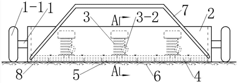
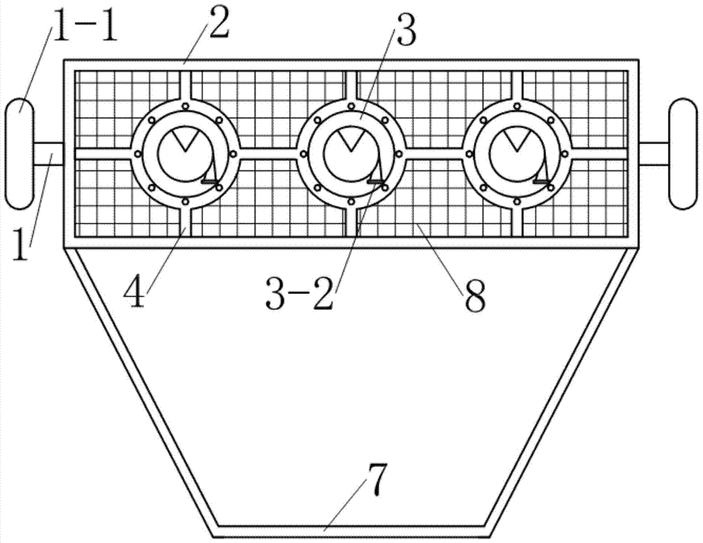
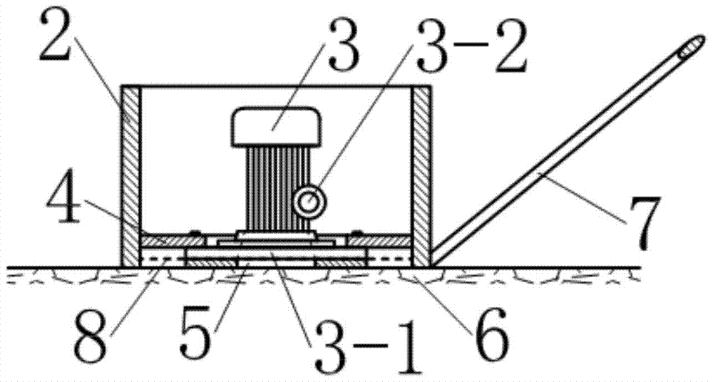
[0023] see Figure 1~3 , the grouting equipment in this example includes a vehicle frame 1, a slurry storage box 2 and a vacuum pump 3 located on the vehicle frame; wherein the slurry storage box 2 is a cuboid metal box with an open top and bottom, and the metal The box is 1.5m long, 0.7m wide, and 0.5m high. Three rotary vane vacuum pumps 3 (model 2XZ-0.5, working pressure range of 1.0×10 -2 ~1.5×10 -2 Pa), the three vacuum pumps 3 are fixed on the inside of the pulp storage box 2 by the bracket 4. The vehicle frame 1 is composed of a pulp storage box 2, two axles arranged at two ends of the pulp storage box 2 and wheels 1-1 arranged at the ends of the axles. When the grouting equipment is placed on the road surface 6, the open edge of the bottom of the slurry storage box 2 is close to the road surface 6; the inlets 3-1 of the three vacuum pumps 3 are all close to the road surface 6, and the outlet 3-1 is close to the road surface 6. 2 is directly exposed in the pulp storag...
example 2
[0027] see Figure 5-7 , the vehicle frame 1 in this example is a flat type vehicle frame with four wheels 1-1, along its moving direction on the vehicle frame 1, a rotary vane vacuum pump 3 (model 2XZ-0.4 type, working pressure The range is 5.0×10 -2 ~6.5×10 -2 Pa), the other end is provided with a rectangular through groove, and the described pulp storage box 2 is located in this through groove, and its shape and size are identical with example 1, and the two ends of the pulp storage box 2 are welded on the through groove respectively by two connecting rods. On both sides, the edge forming its bottom opening is in close contact with the road surface 6 .
[0028] see Figure 5-7 , the inlet flange of the vacuum pump 3 links to each other with a suction pipe 3-3 extending above the pulp storage box 2, and the outlet flange links to each other with a discharge pipe 3-4 extending to the inside of the slurry storage box 2. The suction pipe 3-3 is provided with three branch pi...
example 3
[0029] Example 3 (this example is the experimental example of verifying the grouting equipment effect of the present invention)
[0030] 1. Purpose of the experiment
[0031] Verify the grouting effect of the grouting equipment described in Example 1.
PUM
 Abstract
Description
Claims
Application Information
 - R&D
- Intellectual Property
- Life Sciences
- Materials
- Tech Scout
- Unparalleled Data Quality
- Higher Quality Content
- 60% Fewer Hallucinations
Browse by: Latest US Patents, China's latest patents, Technical Efficacy Thesaurus, Application Domain, Technology Topic, Popular Technical Reports.
© 2025 PatSnap. All rights reserved.Legal|Privacy policy|Modern Slavery Act Transparency Statement|Sitemap|About US| Contact US: help@patsnap.com


