Eureka AIR delivers breakthrough ideas for toughest innovation challenges, trusted by R&D personnel around the world.

Vehicle laminated glass with low-resistance region in heating region

A laminated glass, low-resistance technology, used in vehicle maintenance, vehicle cleaning, transportation and packaging, etc., can solve problems such as low busbar height, heating, and uneven heating, reduce the risk of burnout, and solve uneven heating. , the effect of reducing the chance of burning

Inactive Publication Date: 2016-02-17
FUJIAN WANDA AUTOMOBILE GLASS IND
View PDF11 Cites 6 Cited by
  • Summary
  • Abstract
  • Description
  • Claims
  • Application Information

AI Technical Summary

Problems solved by technology

[0019]1. For automotive glass, it usually has a radian and is an irregular rectangle. On this basis, the visible light transmittance is guaranteed to be >=70%, and the height of the busbar is as high as possible Small, to solve the problem of uniform heating of the film layer in the main viewing area
[0020]2. Solve the problem of uneven heating in the heating zone at the static position of the wiper, and reduce the chance of the wiper motor being burned

Method used


Image

  • Vehicle laminated glass with low-resistance region in heating region
  • Vehicle laminated glass with low-resistance region in heating region
  • Vehicle laminated glass with low-resistance region in heating region

Examples


Embodiment 1

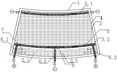
[0068] As shown in the figure, the solution includes a glass substrate 1, which includes an electrothermal film layer 2 that removes the film around the periphery to prevent oxidation and forms the film removal boundary 4, and the wiper rest position heating zones 2.1, 2.2 for auxiliary heating; Two roughly parallel upper busbars 3.1 and lower busbars 3.2 are arranged on the film layer 2; a non-conductive partition bar 5 is arranged under the lower busbar, so that the heating area at the rest position of the wiper is not connected to the lower busbar, and at the same time extends to the surrounding film removal area, The non-conductive dividing strip can be formed by methods such as laser film removal, physical masking before coating, or chemical etching, and is preferably cut by laser; the non-conductive dividing strip 5 can have a certain width, or can be a thin line. At least one second busbar 6.1 or 6.2 is drawn out from the heating zone at the rest position of the wiper to...

Embodiment 2

[0071] figure 2 for similar figure 1 structure, when the distance between the upper and lower busbars is less than or equal to 800mm, it is preferable to use a similar figure 2 The structure does not apply a low-resistance area at the position of the glass bulk. Others are with embodiment 1.

Embodiment 3

[0073] image 3 for similar figure 2 structure, when the distance between the upper and lower busbars is less than or equal to 700mm, it is preferable to use a similar image 3 The structure of the busbar under the glass does not need to set a mesh structure. Others are with embodiment 1.


PUM

PropertyMeasurementUnit
Resistanceaaaaaaaaaa
Diameteraaaaaaaaaa

Abstract

Provided is a vehicle laminated glass with low-resistance regions in a heating region. The peripheral edges of an electrothermal film (2) on a glass substrate (1) are provided with edge non-conductive regions. The electrothermal film (2) is provided with an upper bus (3.1) and a lower bus (3.2). The lower bus (3.2) divides the electrothermal film (2) into a primary vision heating region and a windscreen wiper rest position heating region (2.1). The windscreen wiper rest position heating region (2.1) is provided with a plurality of low-resistance regions. Each low-resistance region is formed by a plurality of low-resistance assemblies (7). The resistance of the low-resistance assemblies is smaller than the resistance of the electrothermal film. Technical effects of the glass are that through arranging the low-resistance regions, a problem of nonuniform heating of arc glass is solved, and risks that a windscreen wiper motor is burnt down are reduced. A segment of mesh bus is arranged on the lower bus, heating power distribution positions can be optimized and defrosting and deicing performance is improved.

Description

technical field [0001] The invention relates to the technical field of electric heating of automobile glass, in particular to an automobile laminated glass with a heating region provided with a low-resistance region. Background technique [0002] The invention relates to a laminated glass, in particular to windshield glass, side window glass, rear glass and skylight glass of vehicles. This type of glass consists of a single pane of window glass bonded to another single pane of glass with a clear plastic such as polyvinyl butyral (PVB). [0003] At present, there are roughly two heating methods on the market for the front glass of automobiles: [0004] 1. Print the silver-containing conductive solution (hereinafter referred to as "silver paste") on the glass by screen printing and then bake it. Use welding or pasting to make electrical connections, and connect the positive and negative poles of the power supply to allow the current to pass through. To achieve the effect of ...

Claims


Application Information

Patent Timeline
IPC IPC(8): B60S1/02
Inventor 尚贵才吴礼德王科研毛胤达商太友
Owner FUJIAN WANDA AUTOMOBILE GLASS IND
Why Eureka
Eureka Blog
Learn More