Eureka AIR delivers breakthrough ideas for toughest innovation challenges, trusted by R&D personnel around the world.

Resonant wireless power supply system for high-voltage power transmission line

A high-voltage transmission line, wireless power supply technology, applied in circuit devices, electrical components, etc., can solve the problems that terminal equipment cannot obtain reliable energy guarantee, limit smart grid monitoring and management, and distributed energy instability. The effect of reliable power supply, simple structure and convenient installation

Inactive Publication Date: 2016-02-10
WUHAN UNIV
View PDF4 Cites 12 Cited by
  • Summary
  • Abstract
  • Description
  • Claims
  • Application Information

AI Technical Summary

Problems solved by technology

However, energy issues are always the key issues limiting smart grid monitoring and management
Most of the traditional solutions use distributed energy such as wind energy and solar energy, but the inherent instability of distributed energy makes it impossible for terminal equipment to obtain reliable energy guarantees, and the problem is even more serious in the environment with more rainy weather in the south
On the other hand, there is sufficient power on the high-voltage transmission / distribution line, but due to insulation requirements, it cannot directly take power from the high-voltage side, thus forming a prominent contradiction.

Method used


Image

  • Resonant wireless power supply system for high-voltage power transmission line
  • Resonant wireless power supply system for high-voltage power transmission line
  • Resonant wireless power supply system for high-voltage power transmission line

Examples


Embodiment Construction

[0034] The technical solutions of the present invention will be described in detail below in conjunction with the accompanying drawings.

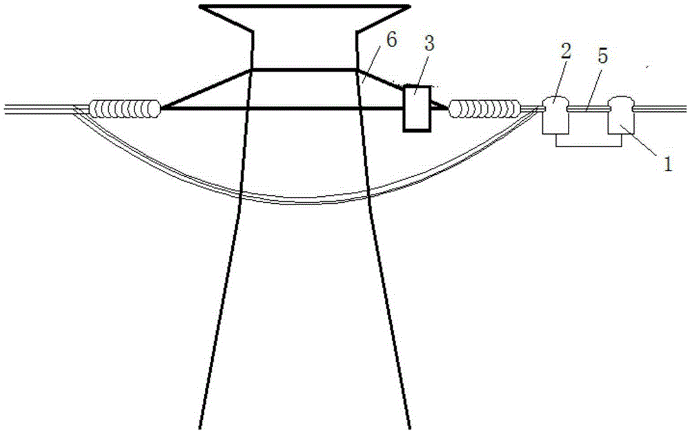
[0035] See Figure 1~2 , The resonant wireless power supply system of the present invention includes a high-voltage power taking device (1), a high-frequency power transmitting device (2) and a high-frequency power receiving device (3), a high-voltage power taking device (1) and a high-frequency power transmitting device (2 ) is installed on the high-voltage line (5), and the high-frequency power receiving device (3) is installed on the tower (6) and supplies power to the load online monitoring device (4).

[0036] The high-frequency power transmitting device includes a high-frequency inverter unit and a high-frequency power transmitting coil, and the high-frequency power receiving device includes a high-frequency power receiving coil and a high-frequency rectifying drive unit. The high-voltage power-taking device obtains alternating curre...


PUM


Abstract

The invention discloses a resonant wireless power supply system for a high-voltage power transmission line. The resonant wireless power supply system comprises a high-voltage electricity taking device, a high-frequency electric power transmitting device and a high-frequency electric power receiving device, wherein the high-voltage electricity taking device and the high-frequency electric power transmitting device are arranged in a high voltage circuit; the high-frequency electric power receiving device is provided with a rod tower and used for powering an online load monitoring device; a high-frequency inversion unit adopts an MOS pipe as a switch pipe, adopts a single-phase full-bridge inversion circuit and is formed by connecting two bridge arms in parallel, each bridge arm consists of an upper bridge arm and a lower bridge arm, and the upper bridge arm and the lower bridge arm of the same bridge arm cannot be simultaneously switched on; a high-frequency rectification drive unit comprises a rectification bridge, the rectification bridge is uncontrolled full-bridge rectification and consists of four pairs of schottky diode pairs, and the schottky diode pair is formed by connecting two schottky diodes in parallel. The resonant wireless power supply system is simple in structure, convenient to install, capable of directly taking electricity from the high voltage circuit and capable of guaranteeing the normal operation of a circuit monitoring device.

Description

technical field [0001] The invention belongs to the technical field of resonant wireless energy transmission, in particular to a resonant wireless power supply system for high-voltage transmission lines. Background technique [0002] High-voltage and ultra-high-voltage power grid monitoring terminals are crucial to ensure the stable operation of the power grid, and are an indispensable part of a modern power grid characterized by informatization, automation, and interaction. However, energy issues are always the key issues that limit smart grid monitoring and management. Most of the traditional solutions use distributed energy such as wind energy and solar energy, but the inherent instability of distributed energy makes it impossible for terminal equipment to obtain reliable energy guarantees. The problem is even more serious in the environment with more rainy weather in the south. On the other hand, there is sufficient power on the high-voltage transmission / distribution li...

Claims


Application Information

Patent Timeline
Patent Type & Authority Applications(China)
IPC IPC(8): H02J50/10
Inventor 周洪胡文山邓其军蒋燕高星冉汪云龙陈晶谢雄威高立克吴智丁
Owner WUHAN UNIV
Why Eureka
Eureka Blog
Learn More