Article transfer device

A technology for transferring devices and articles, which is applied to conveyor articles, transportation and packaging, etc., can solve the problems of maintenance costs, operating costs, and deal with contamination of articles, and achieves a low operating cost and low possibility of articles being contaminated. Effect

Active Publication Date: 2016-02-10
FAB TOYAMA
View PDF9 Cites 6 Cited by
  • Summary
  • Abstract
  • Description
  • Claims
  • Application Information

AI Technical Summary

Problems solved by technology

Therefore, problems such as maintenance costs, running costs, and contamination of processed items occur.

Method used


Image

  • Article transfer device
  • Article transfer device
  • Article transfer device

Examples


Embodiment Construction

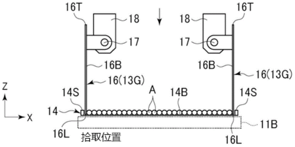
[0045] Hereinafter, embodiments of the present invention will be described with reference to the drawings. figure 1 It is a partial perspective view of a transfer system using a transfer device according to an embodiment of the present invention. also, figure 1 Only the drive system on one side of the transfer device is shown in the figure.

[0046] The conveyance system 10 of the present embodiment includes a pallet conveyance conveyor 11 and a product discharge conveyor 12 . A transfer device 13 according to the present embodiment for transferring articles A between the two conveyors is installed between the pallet conveying conveyor 11 and the product discharge conveyor 12 . The conveyance surface of the product discharge conveyor 12 is arranged at a position higher than the conveyance surface of the pallet conveyance conveyor 11, and both conveyors 11 and 12 are arranged such that their conveying directions are perpendicular to each other.

[0047] The tray conveyance c...


PUM


Abstract

The invention provides an article transfer device which can transfer a plurality of articles at each batch without dispersing the articles and reduces the possibility of contaminating and polluting the articles as well as the costs of maintenance and operation. An elevator (15) is utilized to transport loading trays on the first delivering machine (11A) and a second delivering machine (12B) and the second delivering machine (11B) to the pickup device right below a shifting device (13); a pair of scooping-up-and-guiding parts (13G) are inserted into the two sides of the rod-shaped article (A) in order to scoop up the article (A); the empty-loaded trays (14) and the second delivering machine (11B) are descended to the transportation position through the elevator (15); the product discharging delivering machine (15) is extended to the reception position below the shifting position (13) from the avoiding position so as to enable the scoop-up-guiding part (13G) to perform backward driving relative to the scooping up action, and the scooped up product is discharged to the product discharging delivering machine (12). The product discharging delivering machine (12) is driven to discharge the product along the Y axis.

Description

technical field [0001] The present invention relates to a transfer device for delivering a plurality of articles stored on a tray or the like to another place. Background technique [0002] For example, a transfer device using vacuum suction is known as an unloader that takes out retort-processed retort pouches from a tray and transfers them to a subsequent process. However, in the method of vacuum suction, there is a problem that a part of the retort pouch remains in the tray due to a mistake in taking it out. Therefore, conventionally, the unloaded tray is turned over by an inversion device to recover the retort pouch remaining in the tray (Patent Document 1). [0003] prior art literature [0004] Patent Document 1: JP-A-2005-132553 Contents of the invention [0005] However, the mechanism for inverting the tray and its driving mechanism are complicated and difficult to clean. Therefore, there arise problems of maintenance costs, running costs, and contamination of ...

Claims


Application Information

Patent Timeline
Patent Type & Authority Applications(China)
IPC IPC(8): B65G47/52
Inventor 砂田雅弘石井正章
Owner FAB TOYAMA
Why Eureka
Try Eureka