Battery thermal management device and manufacture method thereof

A battery thermal management and battery technology, applied in fuel cells, secondary batteries, circuits, etc., can solve the problems of long heat conduction path, large heat transfer resistance, large temperature difference, etc., achieve uniform temperature, improve heat transfer efficiency, and vertically The effect of temperature uniformity

Inactive Publication Date: 2016-02-03
谢彦君
View PDF3 Cites 8 Cited by
  • Summary
  • Abstract
  • Description
  • Claims
  • Application Information

AI Technical Summary

Problems solved by technology

The currently used battery cooling methods are mainly liquid cooling and wind cooling. Wind cooling is to take the heat of the battery away through the exhaust fan through the wind generated by movement. However, this cooling method is not suitable for high discharge rate and high temperature operating environments.
Liquid cooling system such as figure 1 As shown, driven by the water pump D, the cooling liquid flows through the heat exchanger C and the battery heat conduction plate B at the bottom of the battery pack A to dissipate the heat inside the battery, but the heat inside the battery needs to be transferred through the electrodes and electrolytes in the battery It is transferred to the battery heat conduction plate B at the bottom of the battery in the vertical direction, and the heat conduction path is long, resulting in large heat transfer resistance, low heat transfer efficiency, large temperature difference in the vertical direction, and strict requirements on the performance of the external cooling system; and the battery The cooling liquid inside the heat conduction plate B flows through the bottom of each battery pack A sequentially, and the temperature of the cooling liquid flowing through the heat conduction plate B of each battery is inconsistent, resulting in a large temperature difference between the battery pack A and the battery pack A, which cannot be guaranteed Uniformity of temperature from cell to cell

Method used


Image

  • Battery thermal management device and manufacture method thereof
  • Battery thermal management device and manufacture method thereof
  • Battery thermal management device and manufacture method thereof

Examples


Embodiment Construction

[0046] The following will clearly and completely describe the technical solutions in the embodiments of the present invention with reference to the accompanying drawings in the embodiments of the present invention. Obviously, the described embodiments are only some of the embodiments of the present invention, not all of them. Based on the embodiments of the present invention, all other embodiments obtained by persons of ordinary skill in the art without making creative efforts belong to the protection scope of the present invention.

[0047] It should be noted that, in the case of no conflict, the embodiments of the present invention and the features in the embodiments can be combined with each other.

[0048] The present invention will be further described below in conjunction with the accompanying drawings and specific embodiments, but not as a limitation of the present invention.

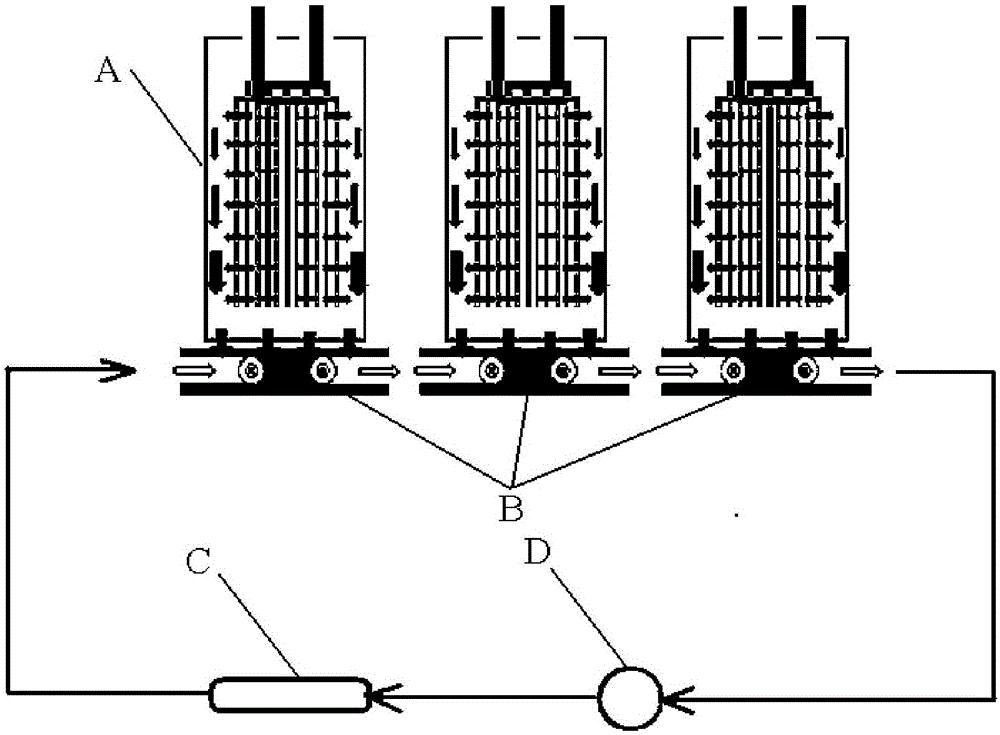
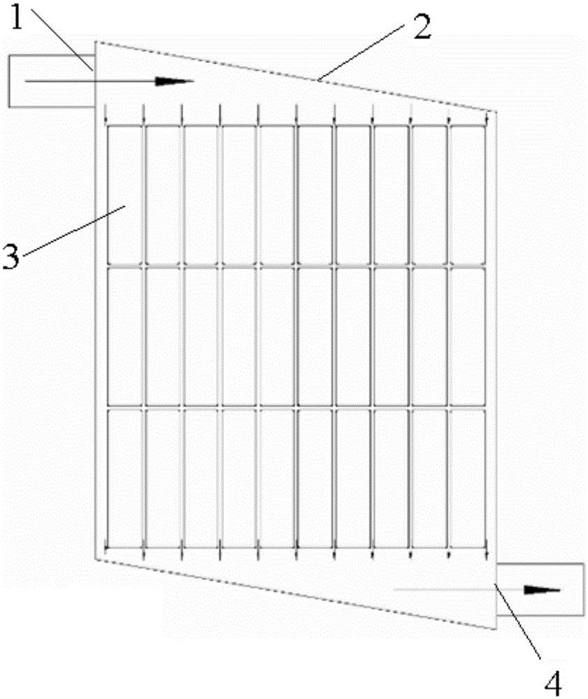
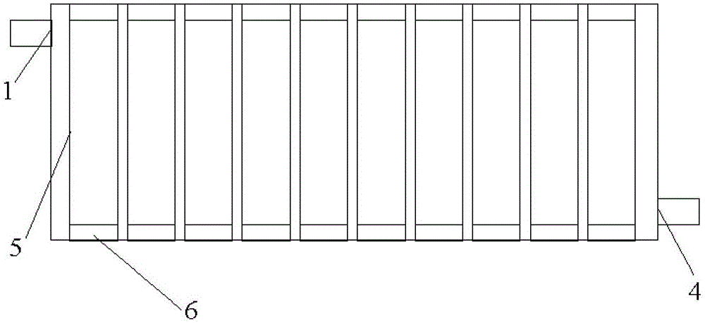
[0049] Such as figure 2 and image 3 As shown, a battery thermal management device include...


PUM


Abstract

The invention discloses a battery thermal management device and a manufacture method thereof. The battery thermal management device comprises batteries, sleeves, a main body and a plurality of mounting holes, wherein the sleeves are used for accommodating the batteries, and are matched with the batteries in size; the main body adopts a sealed structure formed by an upper cover plate, a lower cover plate and side walls, and is used for accommodating cooling liquid; a liquid inlet and a liquid outlet are formed in the main body; the mounting holes are formed in upper cover plate and / or the lower cover plate; the sections of the sleeves are matched with the mounting holes in size; at least one end part of each sleeve is fixed in the corresponding mounting hole in a sealing manner, so that the outer surfaces of the sleeves are soaked in the cooling liquid; an insulation layer is arranged between the sleeves and the batteries. According to the invention, all the sleeves carrying the batteries are soaked in the cooling liquid, so that the purposes that the longitudinal temperature of the batteries is uniform and the temperature among the batteries is uniform are achieved, and the heat exchange efficiency of batteries is improved.

Description

technical field [0001] The present invention relates to the field of heat exchange equipment for power storage batteries of electric vehicles, gasoline-electric hybrid vehicles, or fuel cell vehicles, and in particular to a battery heat management device and a manufacturing method of the battery heat management device. Background technique [0002] As the power source of electric vehicles, power batteries are a key part of improving vehicle performance and reducing costs. Their temperature characteristics directly affect the performance, life and durability of vehicles. Lithium-ion batteries have large specific energy, long cycle life, and Low efficiency, wide allowable operating temperature range, good low temperature effect and other advantages are currently the preferred power battery. Therefore, it is necessary to maintain the temperature uniformity among each battery while ensuring that each single battery in the battery works within a reasonable temperature range. The ...

Claims


Application Information

Patent Timeline
Patent Type & Authority Applications(China)
IPC IPC(8): H01M10/617H01M10/625H01M10/6567H01M8/04029
CPCH01M8/04029Y02E60/50
Inventor 谢彦君
Owner 谢彦君
Why Eureka
Try Eureka