Damper device for vehicle

A shock absorber, vehicle technology, applied in springs/shock absorbers, clutches, friction clutches, etc., can solve problems such as difficulty in reducing torsional resonance rumble noise and clanging noise

Inactive Publication Date: 2016-02-03
TOYOTA JIDOSHA KK
View PDF4 Cites 0 Cited by
  • Summary
  • Abstract
  • Description
  • Claims
  • Application Information

AI Technical Summary

Problems solved by technology

Therefore, it is difficult to achieve both the reduction of torsional resonance and the reduction of rumble and clang noise

Method used


Image

  • Damper device for vehicle
  • Damper device for vehicle
  • Damper device for vehicle

Examples


Embodiment Construction

[0023] Hereinafter, an example of the present invention will be described in detail with reference to the accompanying drawings. Note that each drawing is appropriately simplified and deformed, and thus the dimensional ratios, shapes, and the like of each component are not necessarily depicted in an accurate manner in the following examples.

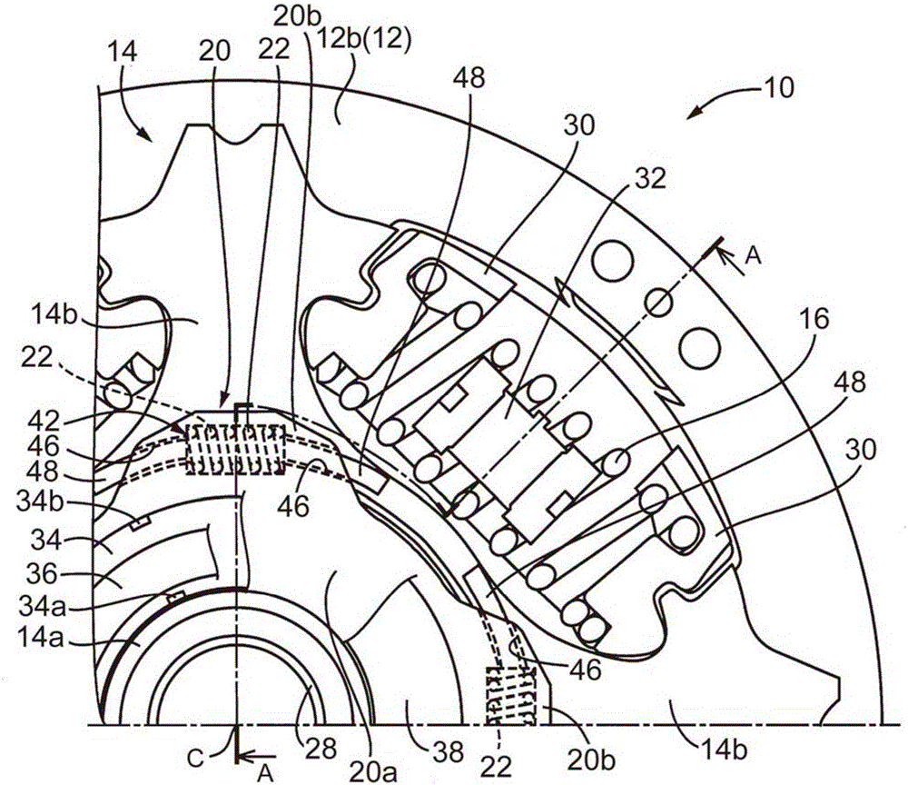
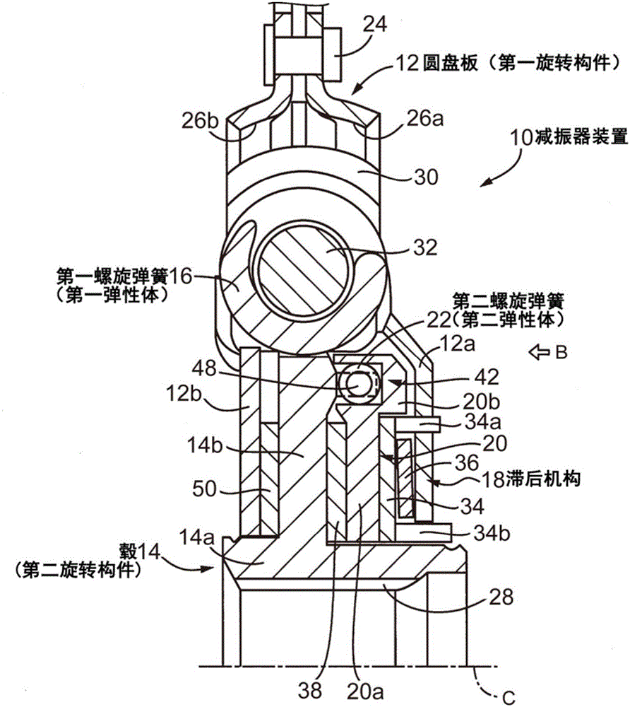
[0024] figure 1 is a front view of the shock absorber device 10 to which the present invention is applied, and figure 2 yes figure 1 The sectional view of the shock absorber device 10 cut along the cutting line A. Note that, since the damper device 10 is configured to be substantially symmetrical in the vertical direction and the horizontal direction, only a part thereof in the circumferential direction (a part of the second quadrant and the first quadrant) is in the figure 1 shown in . in addition, figure 1 From figure 2 The view of the damper device 10 viewed in the direction of arrow B of , and shows a state in which a first p...


PUM


Abstract

A damper device for a vehicle comprises a first rotational member (12), a second rotational member (14), a first elastic body (16), a hysteresis mechanism (18) and a second elastic body (22). The first rotational member (12) is rotatable about a rotational axis (C). The second rotational member (14) is rotatable relatively to the first rotational member (12). The first elastic body (16) is arranged between the first rotational member (12) and the second rotational member (14) without torsion. The hysteresis mechanism (18) is arranged between the first rotational member (12) and the second rotational member (14). The hysteresis mechanism (18) and the second elastic body (22) are connected in series between the first rotational member (12) and the second rotational member (14). The first elastic body (16) is connected in parallel with the hysteresis mechanism (18) and the second elastic body (22) between the first rotational member (12) and the second rotational member (14).

Description

technical field [0001] The present invention relates to a shock absorber device for a vehicle, and more particularly to a structure of a hysteresis mechanism provided in the shock absorber device. Background technique [0002] A shock absorber device that absorbs torque fluctuations is provided in a power transmission path between an engine and drive wheels in a vehicle. In addition, shock absorber arrangements are known which include a hysteresis mechanism. The hysteresis mechanism generates hysteresis torque by friction when the disc plate and the hub constituting the damper device rotate relative to each other, thereby reducing (attenuating) vibration. A damper device disclosed in Japanese Patent Application Publication No. 2009-19746 (JP2009-19746A) is an example of such a damper device. The damper device of JP2009-19746A produces low hysteresis torque when the torsion angle is in a region below a certain value, and the damper device of JP2009-19746A produces a low hys...

Claims


Application Information

Patent Timeline
IPC IPC(8): F16F15/139F16F15/137F16D13/64
CPCF16F15/1238F16F15/129
Inventor 横内由充
Owner TOYOTA JIDOSHA KK
Why Eureka
Try Eureka