Torque support for integrated hoisting machine

Inactive Publication Date: 2013-09-19
SIEMAG TECBERG
View PDF15 Cites 0 Cited by
  • Summary
  • Abstract
  • Description
  • Claims
  • Application Information

AI Technical Summary

Benefits of technology

The present invention provides a torque support for an integrated hoisting machine to prevent deformation and rotational movement of the stator shaft. This is achieved by using separate torque blocks for each turning direction of the hoisting machine, which can be independently adjusted to eliminate backlash and ensure a secure connection between the shaft and the torque support. The pressure elements can also be adjusted in their thickness to ensure optimal contact with the bearing surfaces. The connection between the shaft and the torque support is free from backlash, and the adjustment of the pressure elements can be performed manually or automatically.

Problems solved by technology

As a result, permanent deformation may occur at the bearing section of the shaft.
Such permanent deformation may also result from various dynamic stress situations which are difficult to predetermine
These rotational movements may result in a malfunction of the machine.

Method used


Image

  • Torque support for integrated hoisting machine
  • Torque support for integrated hoisting machine

Examples


Embodiment Construction

[0021]A preferred embodiment of the present invention will now be explained with reference to the drawings. It will be apparent to those skilled in the art from this disclosure that the following description of the embodiment of the present invention is provided for illustration purposes only and not for the purpose of limiting the invention as defined by the appended claims and their equivalents.

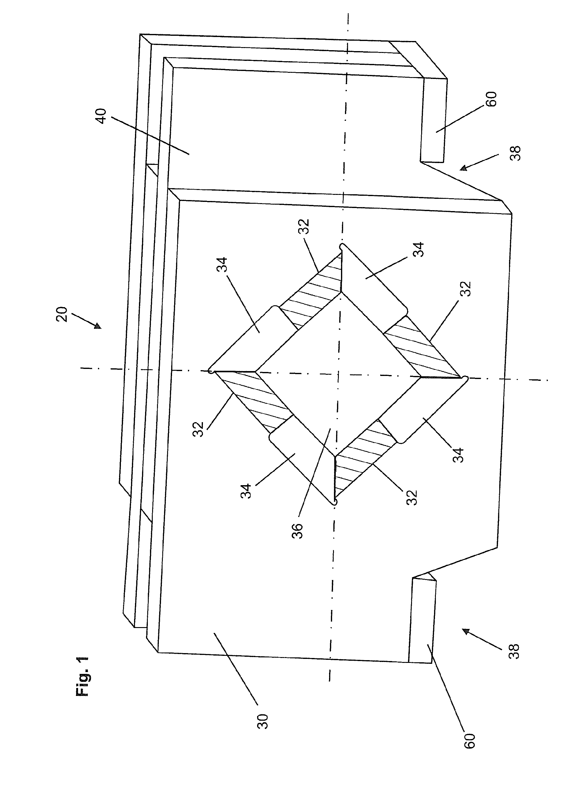
[0022]Referring now to FIG. 1, a torque support 20 for an integrated hoisting machine (not shown) is illustrated. The torque support 20 comprises a torque block 30 for a counter clockwise acting load direction of the hoisting machine 1, a torque block 40 for a clockwise acting load direction of the integrated hoisting machine 1 and two corresponding base elements 60 for the two load directions to which the torque blocks 30 and 40 are fixed.

[0023]The two torque blocks 30 and 40 have the exact same design but are disposed within the torque support 20 rotated by 180° with respect to each other...


PUM


Abstract

Device for bearing the stator shaft of an integrated hoisting machine, with a pedestal for carrying the hoisting loads and a torque support (20) for carrying the turning load, wherein the torque support (20) consists of at least one separate torque block (30, 40) for each turning direction of the hoisting machine, each having a bearing opening (36) with a cross section of flat bearing surfaces, angled with respect to each other, for receiving a bearing section of the stator shaft with a corresponding cross section.

Description

[0001]This invention generally relates to integrated hoisting machines. In particular, the invention relates to a device for bearing the stator shaft of an integrated hoisting machine.[0002]As commonly known in the art, the stator of an integrated hoisting machine is connected to a shaft. This shaft then is fixed to a foundation by means of a pedestal to carry the hoisting loads into the foundation.[0003]The torque support transmits the load of the haulage cables or wire ropes via a portion of the stator shaft having a round cross section and a corresponding bore in the pedestal. The occurring righting moment or reaction is transmitted by means of a polyhedral form-fit connection between a bearing section of the stator shaft and a torque support that is connected to the pedestal. For that purpose the stator shaft is provided with a polyhedral, usually square, section at its end portions which is fixed free from backlash in the torque support with a corresponding polyhedral bearing o...

Claims


Application Information

Patent Timeline
IPC IPC(8): F16C17/02
CPCF16C17/02H02K5/00B66B11/0438
Inventor SCHUBERT, WOLFGANGHOFMANN, KLAUS
Owner SIEMAG TECBERG
Why Eureka
Try Eureka