
Rotary valve stem and control valve

A rotary valve type and control valve technology, which is applied to multi-port valves, valve devices, cocks including cutting devices, etc. , The effect of reducing the difficulty of processing

Active Publication Date: 2017-06-16
LIUZHOU LIUGONG HYDRAULIC COMPONENTS +1
View PDF8 Cites 0 Cited by
  • Summary
  • Abstract
  • Description
  • Claims
  • Application Information

AI Technical Summary

Problems solved by technology

[0005] The technical problem to be solved by the present invention is to provide a rotary valve stem that is easy to process and low in manufacturing cost and a control valve with the valve stem in view of the disadvantages of difficult processing and high manufacturing cost of the existing rotary valve stem.

Method used


Image

  • Rotary valve stem and control valve
  • Rotary valve stem and control valve
  • Rotary valve stem and control valve

Examples


Embodiment Construction

[0024] The specific implementation will be described below in conjunction with the accompanying drawings.

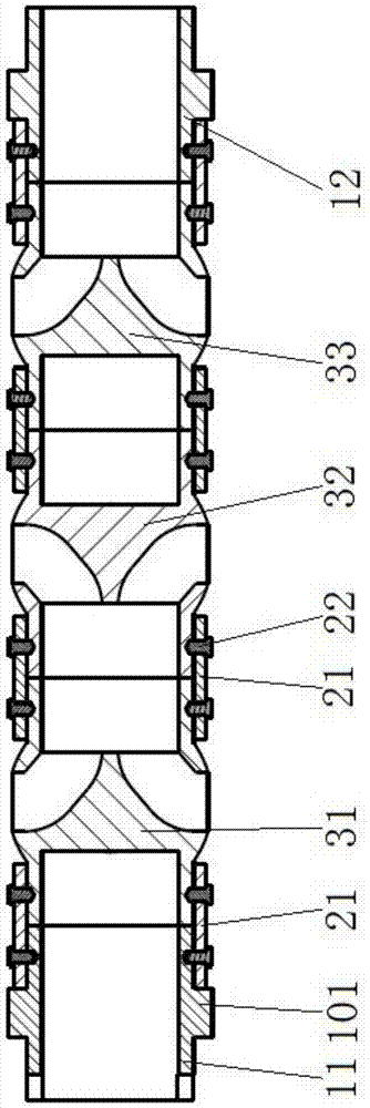
[0025] This embodiment is a rotary valve stem, which can be used for a rotary valve control valve. Such as figure 1 As shown, the rotary valve stem in this embodiment includes five stem segments, and the five stem segments include two positioning segments with the same structure and three stem segments with the same structure and spherical joints The two positioning segments are respectively the left positioning segment 11 and the right positioning segment 12, and the three valve stem segments with spherical joints are the first valve stem segment 31, the second valve stem segment 32, the Three stem segments 33 .

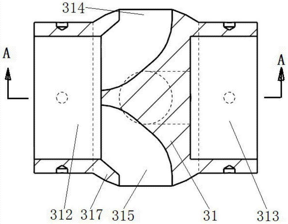
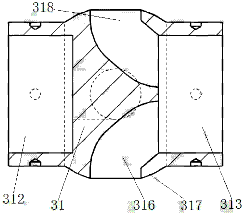
[0026] Such as figure 2 image 3 As shown, there is a spherical joint on the first valve stem section 31, and the spherical joint has a spherical surface 317 surrounding the valve stem section, and four valve stem oil ports are arranged on the spherical s...


PUM


Abstract

The invention relates to a rotary valve type valve rod and a control valve in order to overcome the defects of difficult machining and high fabrication cost of existing rotary valve type valve rods. The rotary valve type valve rod comprises a plurality of valve rod sections; valve rod oil channels are designed in the valve rod sections; the adjacent valve rod sections are sequentially and fixedly connected in the axial direction; the positions, on the axial end faces of the valve rod sections, of the valve rod oil channels are communicated with the outside or with the valve rod oil channels in the adjacent valve rod sections; some valve rod sections are provided with spherical surface joints which are provided with annular spherical surfaces surrounding the valve rod sections; each annular spherical surface is provided with a valve rod oil opening which is communicated with the corresponding valve rod oil channel. The valve rod is mainly composed of the multiple valve rod sections, the machining difficulty of the valve rod sections is low, and molding for forming the valve rod oil channels is simple. Meanwhile, the structures of part of the multiple valve rod sections forming the valve rod can be made to be identical, the interchangeability can be greatly improved, and the machining difficulty can be greatly reduced.

Description

technical field [0001] The invention relates to a hydraulic control component, in particular to a rotary valve stem and a control valve with the stem. Background technique [0002] Among the existing hydraulic control valves, they can be roughly divided into two types, one is the slide valve type, this type of valve includes a valve body, and a valve stem is arranged in the valve cavity of the valve body, the valve stem is cylindrical, and there is a valve stem on it. There are multiple cylindrical shoulders, the shoulders are sealed with the inner wall of the valve cavity, and the valve stem moves axially to block or connect the passages between different oil ports on the valve body. The other type is a rotary valve control valve. This type of valve includes a valve body. A valve stem is installed in the valve cavity of the valve body. There is an oil passage in the stem, and at least one of the outlet and the inlet of the oil passage is set on the side surface of the valv...

Claims


Application Information

Patent Timeline
Patent Type & Authority Patents(China)
IPC IPC(8): F15B13/02F16K11/08F16K5/08
Inventor 初长祥周永飞杨昆蒋拓高名乾高英达柯爱国王宜前
Owner LIUZHOU LIUGONG HYDRAULIC COMPONENTS
Learn More