A traction tool hanger device for replacing the hanger rod of a steel tube truss concrete arch bridge

A steel pipe truss and concrete technology, which is applied in the direction of arch bridge, bridge form, erection/assembly bridge, etc., can solve the problems of high engineering work intensity, high construction cost, complicated construction process, etc. The effect of low strength and convenient standardized construction

Active Publication Date: 2017-03-22
LIUZHOU OVM ENG
View PDF7 Cites 0 Cited by
  • Summary
  • Abstract
  • Description
  • Claims
  • Application Information

AI Technical Summary

Problems solved by technology

Disadvantages: high engineering work intensity, difficult control of on-site welding quality, easy damage to the arch ribs and coating of the original steel pipe, wedge-shaped blocks cannot be used repeatedly, slow progress in demolition and restoration work, large-scale lifting equipment consumes a lot of shifts, and the construction cost is high
[0003] The application publication number is: CN 102926332 A, and the title of the invention is "tool hanger device and replacement method for steel arch bridge hanger replacement" which discloses a tool hanger device for steel arch bridge hanger replacement. It is necessary to weld the limit device near the position of the suspender at each place. It is difficult to control the welding quality on site, and it will damage the arch rib and coating of the original steel structure. The material of the limit device cannot be used for turnover. Partially welded positions are repaired; the number of wire ropes around the arch circle is large, the construction process is complex, the engineering work intensity is high, the progress of demolition and restoration work is slow, the consumption of large lifting equipment is large, and the construction cost is high

Method used


Image

  • A traction tool hanger device for replacing the hanger rod of a steel tube truss concrete arch bridge
  • A traction tool hanger device for replacing the hanger rod of a steel tube truss concrete arch bridge
  • A traction tool hanger device for replacing the hanger rod of a steel tube truss concrete arch bridge

Examples


Embodiment Construction

[0023] The utility model relates to a traction tool hanger device for replacing the hanger of a steel pipe truss concrete arch bridge.

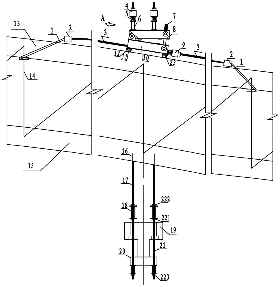
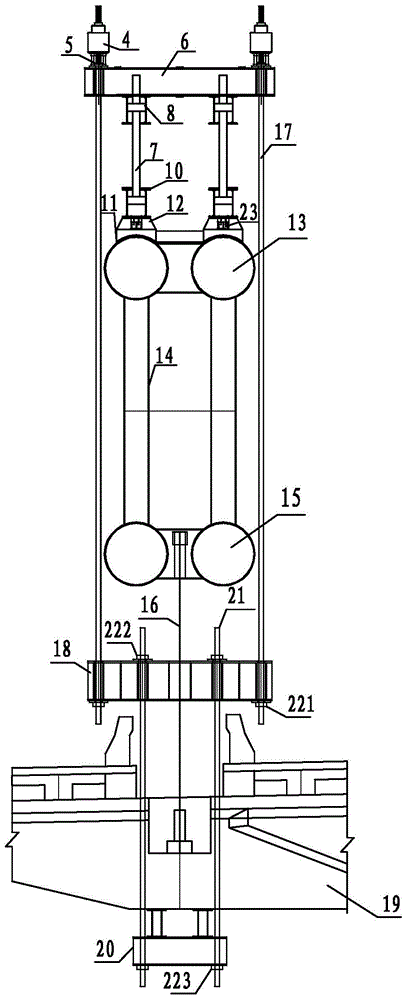
[0024] Such as figure 1 , figure 2 As shown, the traction tool boom device for replacing the boom of the steel pipe truss concrete arch bridge includes a fixed end anchor, a tension end anchor 5, an upper conversion beam 18, a temporary boom 16 and a hanging device, namely: the lower Joist 20;

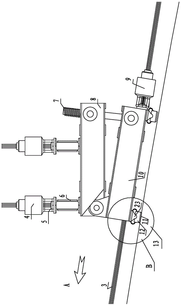
[0025] The difference from the existing tool hanger device is that the traction tool hanger device for replacing the hanger rod of the steel pipe truss concrete arch bridge of the present invention also includes a traction type vault anchorage anti-skid system installed on the arch of the steel pipe truss concrete arch bridge , the traction vault anchorage anti-skid system is composed of a sling 1, an anchor beam 2, a traction cable 3, a traction jack 9, a sliding shoe 12, a skateboard 11, a walking mechanism 10, a leveling mechanism 8, a beam 6 an...


PUM


Abstract

A traction tool hanger device for replacing the hanger of a steel pipe truss concrete arch bridge, including a fixed end anchor, a tension end anchor, an upper transfer beam, a temporary hanger and a hanging device, and a suspension belt, an anchor beam, a traction Cable, traction jack, sliding boots, skateboard, walking mechanism, leveling mechanism, beam and adjustable screw rod for traction arch anchorage anti-slip system; one end of the sling and traction cable is respectively anchored on both sides of the anchor beam, and the traction cable The other end of the sling is connected to the traction jack through the walking mechanism, the other end of the sling is fixed on the web bar, the sliding shoe is installed on the bottom of the walking mechanism, and connected to the walking mechanism through an arc-shaped hinge support; the leveling mechanism is located above the walking mechanism, which can The adjusting screw passes through the leveling mechanism and the traveling mechanism, and the three are connected by a pin shaft. The device does not change the stress system of the original structure during the cable force conversion process of the suspender replacement, has little influence on the stress of the original structure, has low manual work intensity, is convenient for standardized construction, has high work efficiency, and low construction cost.

Description

technical field [0001] The invention relates to a bridge construction machine tool, in particular to a tool suspender device for replacing the suspender of a steel tube truss concrete arch bridge. Background technique [0002] At present, most of the steel tube truss concrete arch bridge suspender replacement cable force conversion devices are mainly temporary suspenders or temporary hoisting devices, and the upper part of the arch needs to be fixed by welding to level the wedge or anti-slip stoppers to achieve the leveling of the arch and facilitate installation. Beam or anti-slip purposes. When the temporary boom or the temporary hoisting device needs to be transferred to the next boom replacement place, the arched beam needs to be hoisted by large-scale lifting equipment. Disadvantages: high engineering work intensity, difficult control of on-site welding quality, easy damage to the arch ribs and coating of the original steel pipe, wedge-shaped blocks cannot be used repe...

Claims


Application Information

Patent Timeline
Patent Type & Authority Patents(China)
IPC IPC(8): E01D21/00E01D4/00
Inventor 窦勇芝韦福堂吕兵张枫林黎祖金
Owner LIUZHOU OVM ENG
Why Eureka
Try Eureka