Pedal mechanism easy to disassemble

A technology of easy disassembly and pedal, applied in the field of automobile control system, can solve the problems of difficult disassembly, hidden danger of driving safety, complicated structure, etc., to achieve the effect of convenient disassembly and ensure the convenience and safety of installation

Active Publication Date: 2016-02-03
ANHUI JIANGHUAI AUTOMOBILE GRP CORP LTD
View PDF6 Cites 0 Cited by
  • Summary
  • Abstract
  • Description
  • Claims
  • Application Information

AI Technical Summary

Problems solved by technology

First of all, this technical solution needs to weld the tube on the pedal arm, which is still not easy to disassemble and has a complex structure. Moreover, when the clutch pedal rotates beyond its normal operating rotation angle range, the clutch pedal can be removed from the support of the bearing frame without any tools. In other words, the driver must ensure that the pedaling force cannot be too large beyond the normal rotation angle, and whether it is the clutch pedal or the brake pedal, the driver usually presses the pedal to the bottom when braking in an emergency. Using this patent application In the case of the technical solution, it is easy to cause the pedal to accidentally detach from the support after emergency braking and fail, which will bring hidden dangers to subsequent driving safety.

Method used


Image

  • Pedal mechanism easy to disassemble
  • Pedal mechanism easy to disassemble
  • Pedal mechanism easy to disassemble

Examples


Embodiment Construction

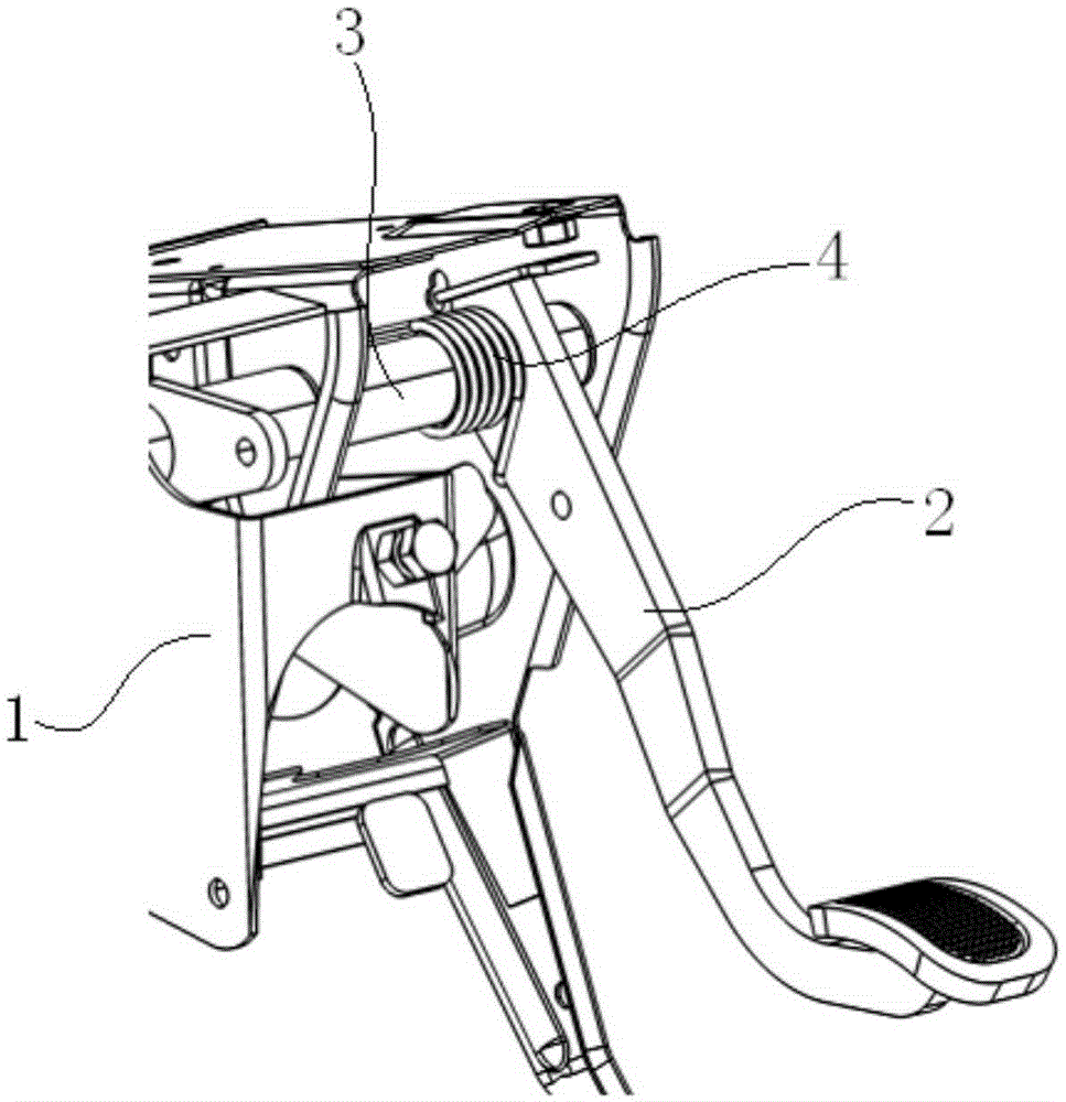
[0024] refer to figure 2 , The easily detachable pedal mechanism of this embodiment includes: a pedal bracket 7 , a return spring 9 , a pedal arm 6 , and a rotating connector 5 . Pin shaft 8 is fixed on the pedal bracket 7 .

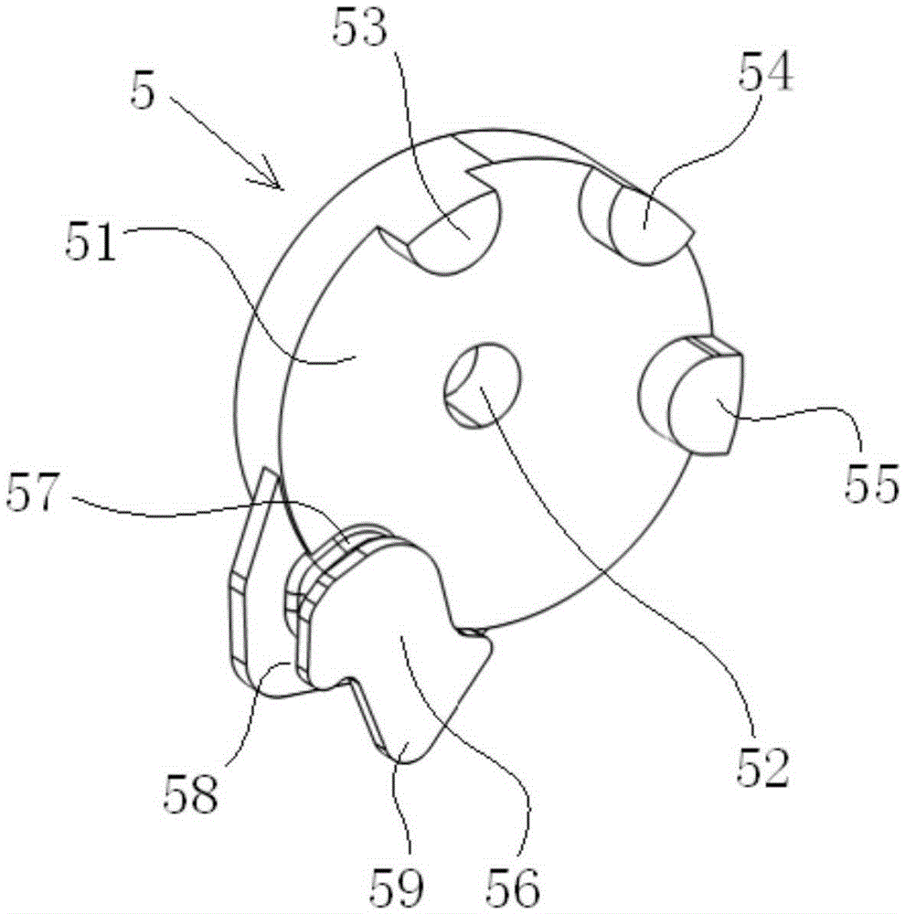
[0025] refer to image 3 with Figure 4 , the main body 51 of the rotating connector 5 is a disk-shaped structure, and the center of the main body 51 has a first pin hole 52 . The main body 51 extends a plurality of first limiting bosses and a second limiting boss 56 to the same side. In this embodiment, there are three first limiting bosses, which are respectively marked as first limiting bosses. Platform 53 , first limiting boss 54 , first limiting boss 55 . The number of the first limiting bosses can be increased or decreased as required, but should be at least two. from Figure 4 It can be seen more clearly that the second limiting boss 56 has a first slot 57 close to the first pin hole 52 and a second slot 58 away from the first pin hole 52 ....


PUM


Abstract

The invention provides a pedal mechanism which is easy to disassemble. The pedal mechanism comprises a pedal bracket, a return spring, a pedal arm, and a rotary connecting component, wherein a pin shaft is fixed to the petal bracket; the main body of the rotary connecting component adopts a disk-shaped structure, a first pin hole is formed in the center of the main body, and the main body extends to the same side to form a plurality of first limiting bosses and a first second limiting boss; the second limiting boss is provided with a first groove which is close to the first pin hole and a second groove which is far away from the first pin hole, a second pin hole is formed in one end of the pedal arm, and first sinks and a second sink are formed in one end of the pedal arm; the pin shaft sequentially penetrates through the first pin hole and the second pin hole, and the first sinks of the pedal arm are matched with the first limiting bosses, and the second sink is matched with the first groove in the second boss; the first limiting bosses and the second limiting boss transmit the rotational movement of the pedal arm, and the first groove limits the axial movement of the pedal arm; one end of the return spring is connected with the pedal bracket, and the other end of the return spring is clamped to the second groove. According to the pedal mechanism disclosed by the invention, the disassembly convenience and the safety of the pedal mechanism are improved.

Description

technical field [0001] The invention relates to the field of automobile control systems, in particular to an easily detachable pedal mechanism. Background technique [0002] There are two types of pedals, the brake pedal and the clutch pedal, in a manual transmission car, while the automatic transmission vehicle cancels the clutch pedal and only retains the brake pedal. The clutch pedal is used to control the separation and combination of the clutch in the transmission system, and the brake pedal is used for braking. The brake pedal is a direct force-bearing mechanism during the braking process, which converts the pedal force into braking force and acts on the four-wheel brakes. figure 1 It is a commonly used brake pedal mechanism at present. The main principle is that the pedal arm 2 rotates with the pin shaft 3 (the pedal arm 2 and the pin shaft 3 are integrally structured), and the pin shaft 3 is installed on the pedal bracket 1, so that the brake pedal The power is tra...

Claims


Application Information

Patent Timeline
Patent Type & Authority Applications(China)
IPC IPC(8): B60T7/06
CPCB60T7/06
Inventor 郑朋辉黄从奎
Owner ANHUI JIANGHUAI AUTOMOBILE GRP CORP LTD
Why Eureka
Try Eureka