safety syringe

A safety syringe and a technology for syringes, applied in the field of syringes, can solve the problems of reducing the reliability of the syringe, the pain of the patient, and the difficulty of pulling back the needle seat, and achieve the effects of eliminating secondary recycling, ensuring safety and reliability, and improving recycling safety.

Inactive Publication Date: 2018-06-05
辛莉
View PDF6 Cites 0 Cited by
  • Summary
  • Abstract
  • Description
  • Claims
  • Application Information

AI Technical Summary

Problems solved by technology

[0004] 1. Since the puncture cone cannot pierce the film area, the upper end surface of the rubber piston cannot be fitted with the inner bottom end surface of the syringe, which results in more air remaining in the syringe. After the drug is drawn , requiring multiple exhaust procedures
[0005] 2. The puncture cone is a solid body, and its own elastic compression is small. In the process of pulling back the needle, if you accidentally use too much force, it is very likely that the puncture cone will be detached from the elastic chuck, and the return of the needle cannot be achieved. shrink
[0006] 3. After the puncture cone has been inserted into the elastic collet, one end surface of the elastic collet cooperates with the end surface with an inclined angle of the puncture cone, so that the elastic collet has a lateral pressure on the needle seat through the puncture cone , resulting in difficulty in pulling back the needle seat. At the same time, the elastic collet will also exert a lateral pressure on the piercing cone, which will easily cause the piercing cone to deform, and then make the needle seat be pulled back into the syringe. When the needle seat does not tilt, which reduces the reliability of the syringe
[0007] 4. When the puncture cone is inserted into the elastic clip hole, it needs to be pushed hard. The puncture cone quickly snaps into the elastic clip hole during this process. Due to the high speed, the medicine cannot be slowly and steadily pushed into the patient's body, which will cause the patient pain and discomfort

Method used


Image

  • safety syringe
  • safety syringe
  • safety syringe

Examples


Embodiment Construction

[0042] The technical solutions in the embodiments of the present invention will be clearly and completely described below in conjunction with specific embodiments and accompanying drawings. Obviously, the described embodiments are only some preferred embodiments of the present invention, not all embodiments. Those skilled in the art can make similar modifications without departing from the connotation of the present invention, so the present invention is not limited by the specific embodiments disclosed below.

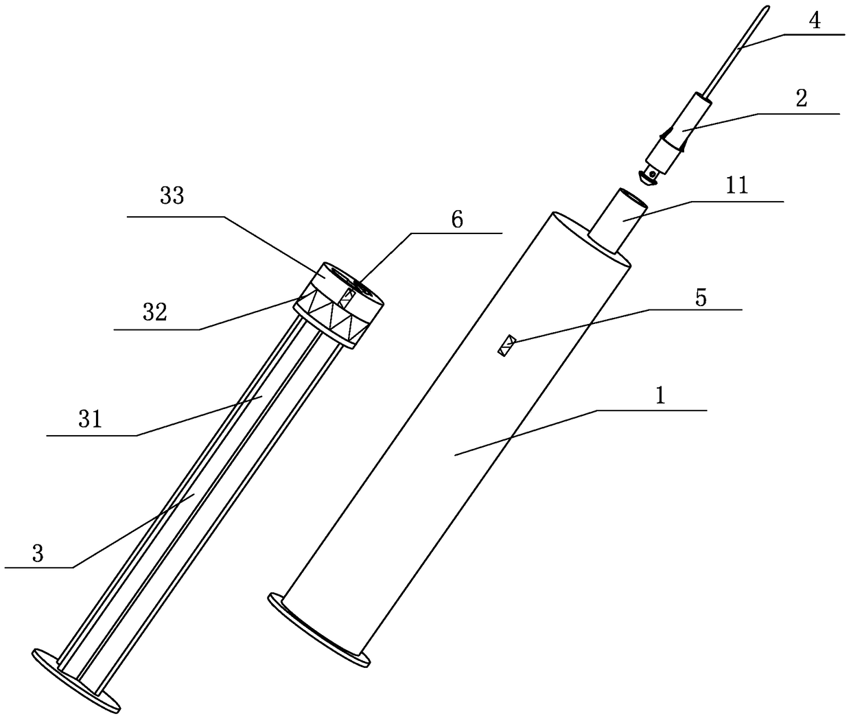
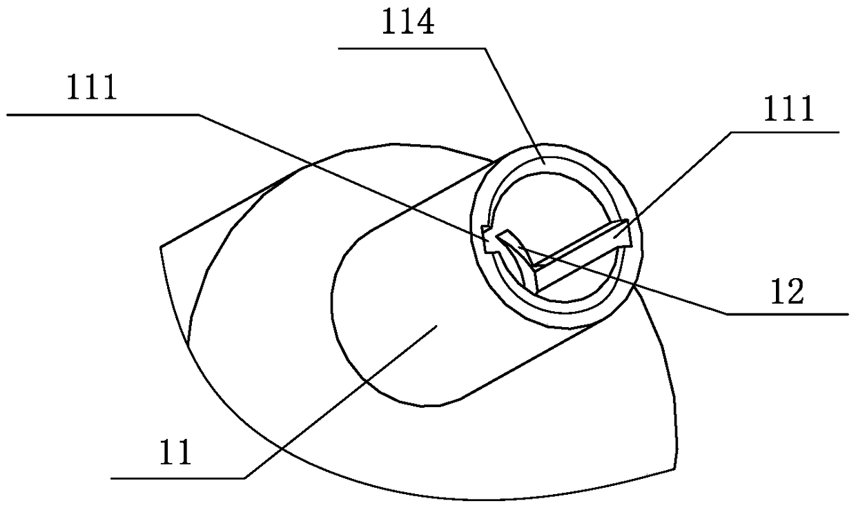
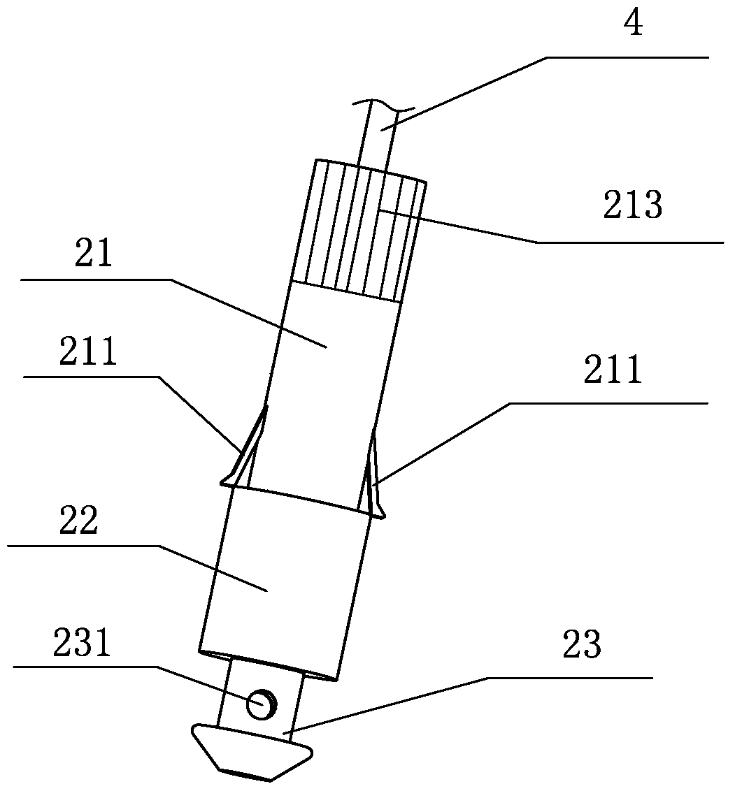
[0043] The present invention provides a safety syringe, which comprises a syringe 1, a piston 3 and an injection needle 4, the upper end of the syringe 1 is provided with an injection end 11 connected to the interior of the syringe 1, and the piston 3 is sleeved on the Inside the syringe 1, the injection needle 4 is set on the injection end 11 through the injection needle base 2. In order to facilitate the injection needle base 2 to slide into the injection end 11 smoot...


PUM


Abstract

The invention discloses a safe syringe. The safe syringe comprises a needle cylinder, a piston and a needle, wherein an injection end communicated with the interior of the needle cylinder is arranged at the upper end of the needle cylinder, the piston is sleeved with the needle cylinder, the needle is fixedly arranged on the injection end through a needle base, the center axis of the injection end is not coaxial with the center axis of the needle cylinder, and a limiting groove is formed in the inner side wall of the injection end. After drug injection is finished with the safe syringe, the needle can be bent in the needle cylinder, so that secondary recovery is avoided and staff infection caused by stabbing or scratching of the needle is avoided during syringe collection.

Description

technical field [0001] The invention relates to an injector, in particular to an injector capable of realizing the retraction of an injection needle. Background technique [0002] In the medical field, syringes are widely used in the injection of liquid medicine and the extraction of blood from patients with some diseases. After the syringe is used, a safety shield is generally placed on the needle of the syringe, and then the syringe is recovered. During the working process of the syringe, once the operation is improper, the staff is easy to be stabbed, and then increases At the same time, when a large number of discarded syringes are stored together, the protective cover of the needle is easy to scratch off. When the staff cleans up the recycled syringes, some exposed needles will affect the recycling work. Injuries to personnel will also increase the possibility of some diseases and infections. For this reason, many medical equipment manufacturers are working on developi...

Claims


Application Information

Patent Timeline
Patent Type & Authority Patents(China)
IPC IPC(8): A61M5/50A61M5/178A61M5/32A61M5/315
Inventor 辛莉
Owner 辛莉
Why Eureka
Try Eureka