
Long-stroke permanent magnet operating mechanism with magnetic bridge and auxiliary weak magnetic coil for high-voltage vacuum circuit breaker

A vacuum circuit breaker and operating mechanism technology, applied in high-voltage air circuit breakers, high-voltage/high-current switches, circuits, etc., can solve the problems of high contact impact speed, long response time of opening and closing speed, etc. The effect of closing speed, shortening start time and reducing air resistance

Active Publication Date: 2016-01-27
SOUTHEAST UNIV
View PDF5 Cites 3 Cited by
  • Summary
  • Abstract
  • Description
  • Claims
  • Application Information

AI Technical Summary

Problems solved by technology

[0003] Purpose of the invention: In order to overcome the deficiencies in the prior art, a long-stroke permanent magnet operating mechanism for a high-voltage vacuum circuit breaker with a magnetic bridge and an auxiliary field-weakening coil is proposed, which solves the problem of opening and closing of the permanent magnet mechanism of a high-voltage vacuum circuit breaker. The speed response time is too long and the impact speed of the contact is too large at the end of opening and closing

Method used


Image

  • Long-stroke permanent magnet operating mechanism with magnetic bridge and auxiliary weak magnetic coil for high-voltage vacuum circuit breaker
  • Long-stroke permanent magnet operating mechanism with magnetic bridge and auxiliary weak magnetic coil for high-voltage vacuum circuit breaker
  • Long-stroke permanent magnet operating mechanism with magnetic bridge and auxiliary weak magnetic coil for high-voltage vacuum circuit breaker

Examples


Embodiment Construction

[0022] The present invention will be further described below in conjunction with the accompanying drawings.

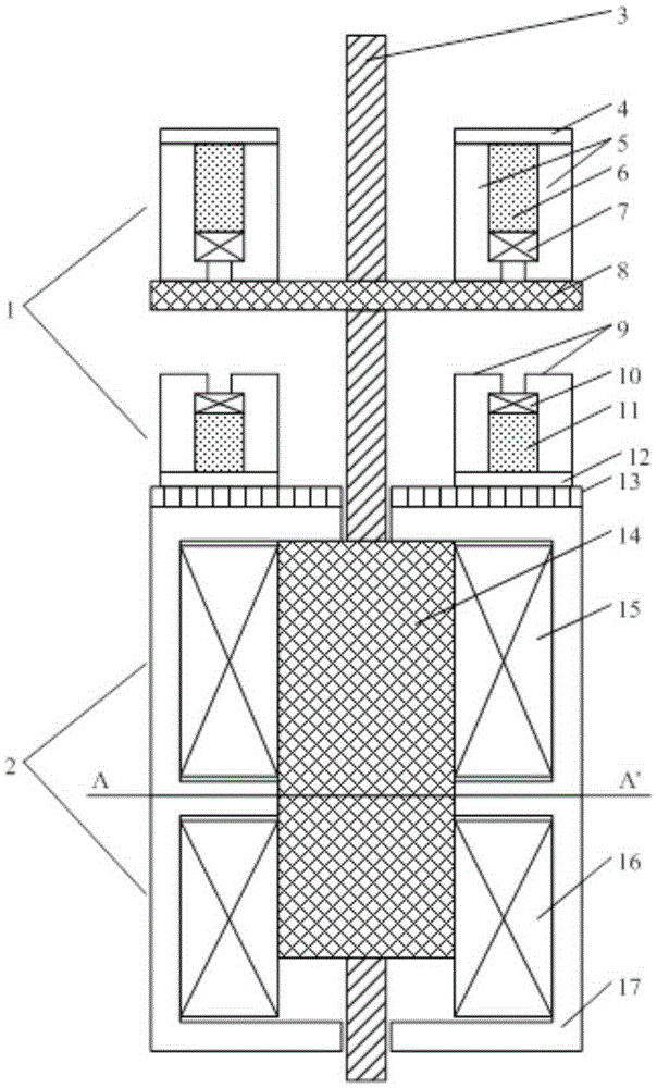
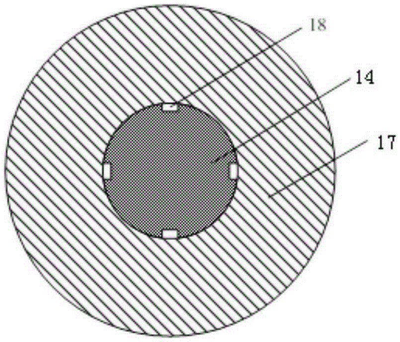
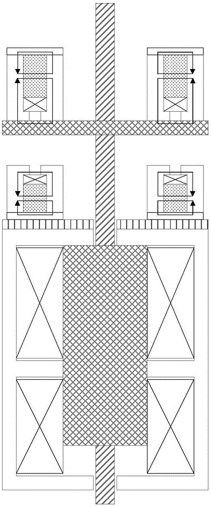
[0023] A long-stroke permanent magnet operating mechanism for a high-voltage vacuum circuit breaker with a magnetic bridge and an auxiliary field-weakening coil. As shown in Figure 1, the permanent magnet mechanism can be a circular permanent magnet mechanism or a square permanent magnet mechanism. It includes a permanent magnet holding mechanism 1, an electromagnetic driving mechanism 2, and a guide rod 3 connected to the moving contact of the circuit breaker. A non-magnetic material gasket 13 is provided between the permanent magnet holding mechanism 1 and the electromagnetic driving mechanism 2, wherein:

[0024] The permanent magnet holding mechanism 1 includes an upper permanent magnet holding mechanism and a lower permanent magnet holding mechanism, the upper permanent magnet holding mechanism and the lower permanent magnet holding mechanism are arranged oppositel...


PUM


Abstract

The invention discloses a long-stroke permanent magnet operating mechanism with a magnetic bridge and an auxiliary weak magnetic coil for a high-voltage vacuum circuit breaker. The mechanism comprises a guide rod connected with a circuit breaker moving contact, a permanent magnet holding mechanism, an electromagnetic driving mechanism, and a non-magnetic material gasket. The permanent magnet holding mechanism comprises an upper magnetic bridge, a switching-on static iron core, a switching-on moving iron core, a switching-on permanent magnet, an upper auxiliary weak magnetic coil, a switching-off static iron core, a switching-off permanent magnet, a lower auxiliary weak magnetic coil, a lower magnetic bridge, and a holding moving iron core. The electromagnetic driving mechanism comprises a switching-on coil, a switching-off coil, a driving static iron core, and a driving moving iron core. The mechanism can reduce the absorption force of the permanent magnet for the holding moving iron core at the switching-off and switching-off starting stages and the absorption force of the permanent magnet for the holding moving iron core at the switching-off and switching-off ending stages, and achieves the starting acceleration and ending deceleration of the moving iron core. Meanwhile, the mechanism is enabled to counteract a part of holding forces of the switching-off permanent magnet and the switching-on permanent magnet at the switching-off and switching-off starting stages through the auxiliary coils, and shortens the switching-off and switching-off starting time.

Description

technical field [0001] The invention relates to a long-stroke permanent magnet operating mechanism for a high-voltage vacuum circuit breaker with a magnetic bridge and an auxiliary field-weakening coil, belonging to the field of high-voltage vacuum circuit breakers. Background technique [0002] Vacuum circuit breakers have been widely used in medium voltage power grids because of their good working performance. Compared with the medium-voltage vacuum circuit breaker, the stroke of the high-voltage vacuum circuit breaker is increased, so higher requirements are put forward for the opening and closing speed of the operating mechanism. In addition, due to the long stroke of the moving contact, the air gap reluctance of the moving iron core driven by the operating mechanism increases when the opening and closing starts, which means that a large current needs to be passed into the opening and closing coil to successfully open and close. Closing operation. The existence of thes...

Claims


Application Information

Patent Timeline
Patent Type & Authority Applications(China)
IPC IPC(8): H01H33/666
CPCH01H33/666
Inventor 房淑华倪海妙杨延举林鹤云
Owner SOUTHEAST UNIV
Learn More