
Intelligent magnetic control low-voltage switch device

A low-voltage switch and magnetic control technology, which is applied in the field of substation management and control, can solve the problem that it is difficult to meet the intelligent and high-performance requirements of low-voltage intelligent circuit breakers, the inability to realize the live pluggable replacement of the secondary control system, and the aging and damage of the secondary control system, etc. problems, to achieve high intelligence, improve device flexibility, and simple structure

Pending Publication Date: 2022-03-18
ZHUHAI XJ ELECTRIC
View PDF0 Cites 0 Cited by
  • Summary
  • Abstract
  • Description
  • Claims
  • Application Information

AI Technical Summary

Problems solved by technology

The primary system and secondary control system of the existing molded case circuit breaker are integrated, which cannot be modularized, and the live pluggable replacement of the secondary control system cannot be realized, and the life of the primary and secondary control systems cannot be synchronized. When it can still work normally, the secondary control system has been aged and damaged, causing the entire circuit breaker to be scrapped, resulting in waste
The traditional molded case circuit breaker control circuit board is not completely isolated from the primary part, and the heat insulation performance is poor. The temperature of the primary part is high when it is working, and the heat will be transferred to the secondary part, which will accelerate the aging of the secondary part.
The spring-type operating mechanism has a complex structure and is easy to wear. The mechanical life is about 20,000 to 50,000 times.

Method used


Image

  • Intelligent magnetic control low-voltage switch device
  • Intelligent magnetic control low-voltage switch device
  • Intelligent magnetic control low-voltage switch device

Examples


Embodiment Construction

[0083] In order to make the purpose, technical solutions and advantages of the present invention clearer, the present invention will be further described in detail below in conjunction with specific embodiments and with reference to the accompanying drawings. It should be understood that these descriptions are exemplary only, and are not intended to limit the scope of the invention. Also, in the following description, descriptions of well-known structures and techniques are omitted to avoid unnecessarily obscuring the concept of the present invention.

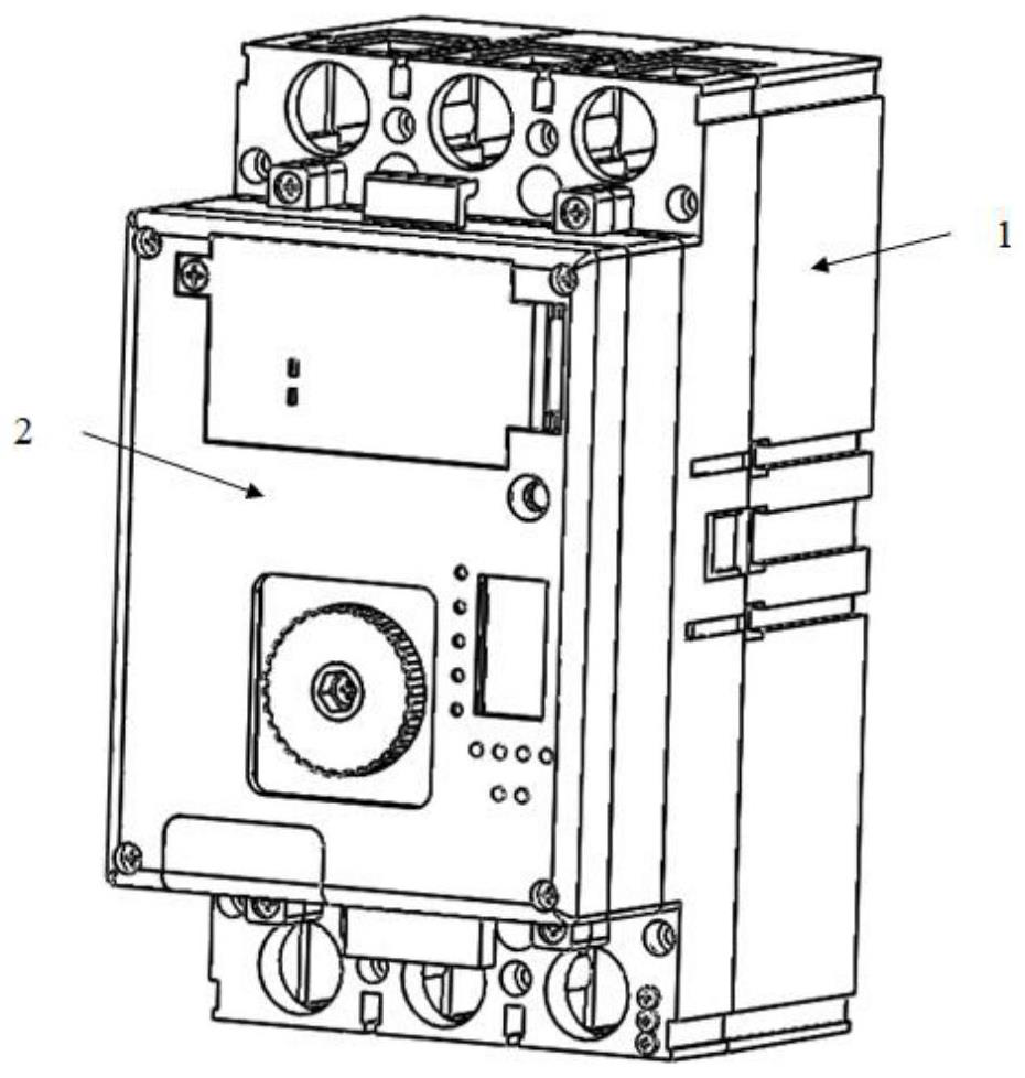
[0084] In a specific embodiment, the present invention provides an intelligent magnetic control low-voltage switch device, such as figure 1 As shown, the intelligent magnetic control low-voltage switch includes a magnetic control primary module and a blade secondary module.

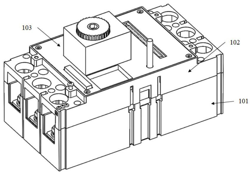
[0085] Specifically, such as figure 2 and image 3 As shown, the magnetically controlled primary module includes a first bottom case 101, a first top ...


PUM


Abstract

An intelligent magnetic control low-voltage switch device comprises a magnetic control type primary module and a blade type secondary module. The magnetic control type primary module comprises a first bottom shell, a first top shell, a plastic shell baffle plate and a bottom flitch plate, and the first bottom shell, the first top shell, the plastic shell baffle plate and the bottom flitch plate form a whole shell frame; automatic opening and closing can be achieved under the size requirement of an original manual molded case circuit breaker, an existing old switch in a transformer area is directly replaced, the opening and closing speed is greatly increased, the mechanical performance is improved, the space capacity of a secondary control module is effectively increased, high intelligence, primary and secondary overall modular design and secondary module heat insulation design are achieved, and the cost is reduced. The secondary control module can be plugged, the secondary module can be replaced without power cut, the operation and maintenance capability of the product is improved, the service life of the primary module and the secondary module is the same, the service life of the device is greatly prolonged, secondary vulnerable components can be plugged independently, the flexibility of the device is improved, and high scientificity and logicality are achieved.

Description

technical field [0001] The invention relates to the technical field of substation management and control, in particular to an intelligent magnetically controlled low-voltage switchgear. Background technique [0002] Molded case circuit breakers are widely used in distribution networks, photovoltaics, new energy vehicle charging piles, and electrical complete sets. The low-voltage molded case circuit breaker is an important part of the distribution network. The operating mechanism of the existing molded case circuit breaker is spring type, with a large number of parts, complex structure, easy wear and low service life, and the traditional molded case circuit breaker is intelligent. Low level of automation, manual operation, slow response, high failure rate. The operating mechanism of the existing molded case circuit breaker is spring type, and the 3P form is manual opening and closing. Under the condition of relatively large rated current, such as above 400A, it is necessary...

Claims


Application Information

Patent Timeline
IPC IPC(8): H01H71/10H01H71/02H01H73/18
CPCH01H71/10H01H71/02H01H73/18
Inventor 海涛尹广俊魏浩铭张维钟子华李斐刚
Owner ZHUHAI XJ ELECTRIC
Learn More