
Excavation transient unloading dynam-relaxing simulation system of jointed rock under different confining pressure

A transient unloading technology for loosening and jointed rock mass, which is applied to the testing of measuring devices, instruments, machines/structural components, etc., and can solve problems such as slow unloading rate, inability to unload loads, and low strain rate of jointed rock mass

Inactive Publication Date: 2016-01-27
WUHAN UNIV OF TECH
View PDF5 Cites 7 Cited by
  • Summary
  • Abstract
  • Description
  • Claims
  • Application Information

AI Technical Summary

Problems solved by technology

Blasting excavation will remove all or part of the initial stress on the excavation surface, thereby changing the geometry of the original jointed rock mass, resulting in changes in its boundary conditions and load conditions, which may cause serious stability or deformation of the jointed rock mass control puzzle
[0003] However, in the past, the problems related to the transient unloading and loosening of jointed rock mass excavation were studied through theoretical analysis and numerical simulation methods, and the strain during the transient unloading and loosening process of jointed rock mass excavation could not be intuitively understood. , displacement and vibration
However, the existing test system for simulating excavation and unloading has a slow unloading rate, and cannot quickly unload the load on the jointed rock mass model, so the strain rate of the jointed rock mass during unloading is low. Does not conform to the actual unloading situation in the project

Method used


Image

  • Excavation transient unloading dynam-relaxing simulation system of jointed rock under different confining pressure
  • Excavation transient unloading dynam-relaxing simulation system of jointed rock under different confining pressure
  • Excavation transient unloading dynam-relaxing simulation system of jointed rock under different confining pressure

Examples


Embodiment Construction

[0046] The specific implementation of the present invention will be further described below in conjunction with the accompanying drawings.

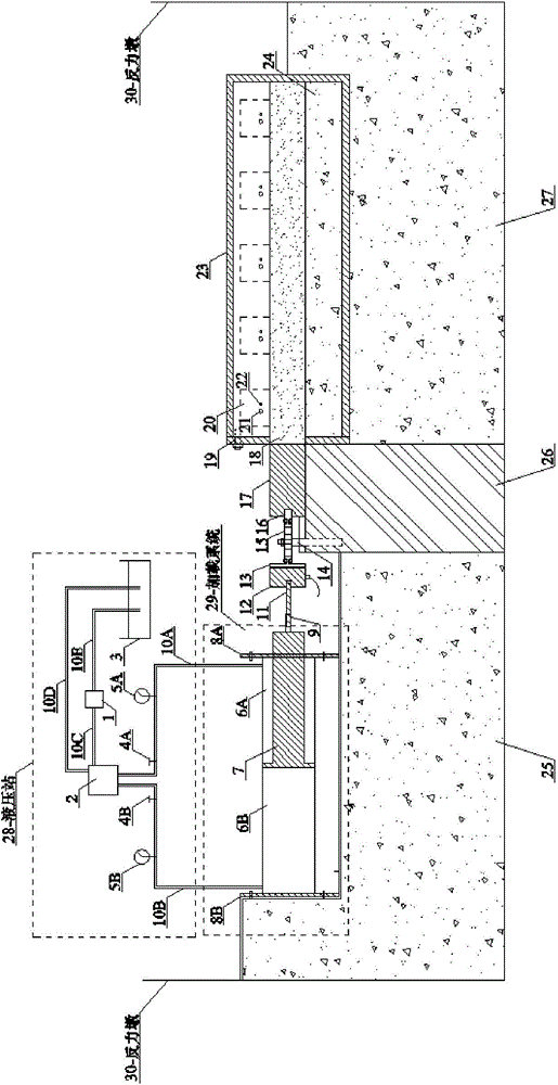
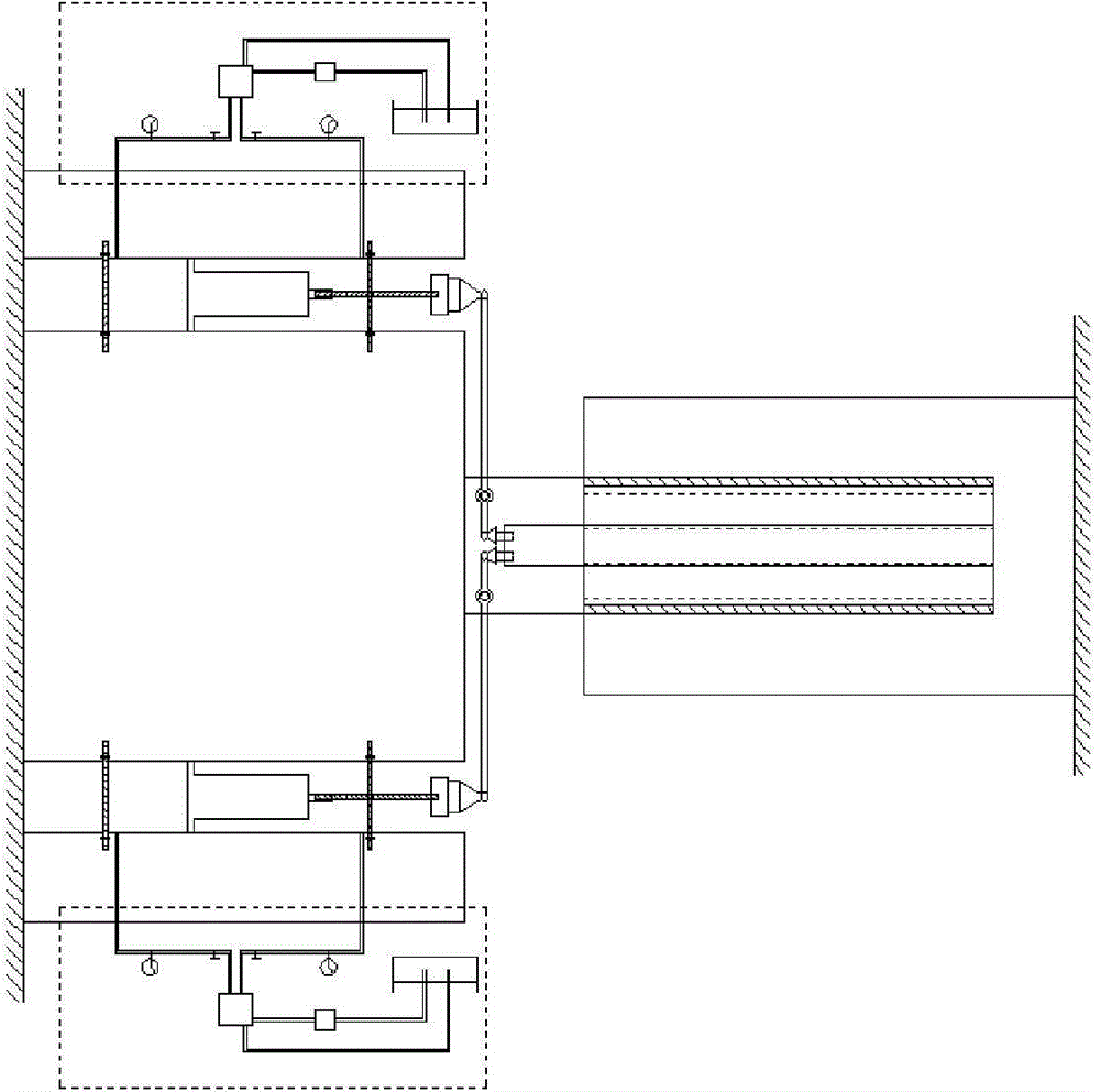
[0047] Such as Figure 1~2 As shown, a jointed rock mass excavation transient unloading loosening simulation system under different confining pressures of the present invention includes: reaction pier 30, hydraulic station 28, loading system 29, loading device support platform 25, lever 15, Lever support 14, transition block 17, transition block pad box 26, test bench with circular groove 27, steel round pipe with one end closed 23, air compressor 38, 120° arc-shaped concrete column 24 with displacement scale mark, arc Shaped air bag 20, jointed rock mass model 18 and monitoring system;

[0048] The loading system 29 is set on the loading device support platform 25, and the hydraulic station 28 provides hydraulic power for the loading system 29 (the loading system can be a hydraulic cylinder); the transition block pad box 26 is located b...


PUM


Abstract

The present invention discloses an excavation transient unloading dynam-relaxing simulation system of jointed rocks under different confining pressures. The system comprises a counter-force pier, a hydraulic pressure station, a loading system, a loading device support platform, a lever, a lever support, a transition block, a transition block cushion box, an experiment table with a round groove, a circular steel tube with one end being closed, an air compressor, a 120-degree arc-shaped concrete column provided with displacement scale marks, arc-shaped air sacs, a jointed rock model and a monitoring system, wherein the arc-shaped concrete column and the arc-shaped air sacs are used for applying a confining pressure to a joint rock body, the loading system is used for applying a horizontal pressure to the jointed rock body, an inner diameter of the arc-shaped concrete column is provided with the displacement scale marks, the arc-shaped concrete column is placed inside the circular steel tube and is used for placing the jointed rock model, and the monitoring system is used for monitoring a simulation process. With adoption of the system provided by the present invention, rapid unloading of the jointed rock module under different confining pressures can be realized, and the jointed rock model can generate large vibrations and a large strain rate, which accords with unloading conditions in practical engineering.

Description

technical field [0001] The invention belongs to the field of geotechnical engineering model experiment devices, and in particular relates to a transient unloading and loosening simulation system for jointed rock mass excavation under different confining pressures. Background technique [0002] Under the long-term geological tectonic movement and human disturbance, various intricate joints with different directions will be formed in the natural rock mass. However, during the blasting and excavation of deep underground engineering, the transient unloading and stress redistribution of the surrounding rock mass are caused by the excavation disturbance, especially when blasting and excavating in the rock mass containing joints, the jointed rock mass usually appears loosening effect. Blasting excavation will remove all or part of the initial stress on the excavation surface, thereby changing the geometry of the original jointed rock mass, resulting in changes in its boundary cond...

Claims


Application Information

Patent Timeline
Patent Type & Authority Applications(China)
IPC IPC(8): G01M99/00
Inventor 李新平黄俊红罗忆王仰君樊伟
Owner WUHAN UNIV OF TECH
Learn More