
Motor and electric device equipped with same

A technology of electric motors and electrical conductivity, which is applied in the field of electric motors and can solve problems such as electric corrosion and shaft voltage collapse

Active Publication Date: 2016-01-20
PANASONIC INTELLECTUAL PROPERTY MANAGEMENT CO LTD
View PDF9 Cites 0 Cited by
  • Summary
  • Abstract
  • Description
  • Claims
  • Application Information

AI Technical Summary

Problems solved by technology

Therefore, if the conventional structure of electrically connecting the stator core of the motor, etc., to the ground wire of the earth is adopted and the problem is solved by adding the structure of the structure, then from the viewpoint of the specifications and characteristics of the motor, it will be further improved. There are difficulties in investigating other topics
[0013] In addition, in the method of electrically shorting the two end caps, providing a dielectric layer on the rotating body, and changing the electrostatic capacity to reduce the shaft voltage, the following problems have been considered: short-circuiting the lead wire between the two end caps, conduction The belt is cut during the production process of the motor or during the use of the motor, and the balance of the shaft voltage in the two end caps collapses and galvanic corrosion occurs

Method used


Image

  • Motor and electric device equipped with same
  • Motor and electric device equipped with same
  • Motor and electric device equipped with same

Examples


Embodiment approach 1

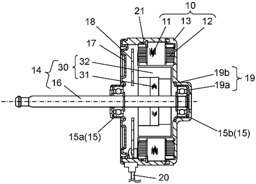
[0039] figure 1 It is a structural diagram showing the cross section of the motor in Embodiment 1 of the present invention. In this embodiment, an example of a motor as a brushless motor for driving a blower fan installed in an air conditioner as an electric device will be described. In addition, in this embodiment, an example of an inner rotor (inner rotor) type motor in which a rotor is rotatably arranged on the inner peripheral side of a stator will be described.

[0040] exist figure 1 Among them, the stator winding 12 is wound on the stator core 11 via a resin 21 as an insulator, and the resin 21 insulates the stator core 11 . Also, this stator core 11 is molded together with other fixing members by insulating resin 13 as a molding material. In the present embodiment, the stator 10 having an approximately cylindrical outer shape is constituted by integrally molding these members in this manner.

[0041] The rotor 14 is inserted inside the stator 10 with a gap between ...

Embodiment approach 2

[0091] As an example of an electric device equipped with a motor according to the present invention, first, the configuration of an air conditioner indoor unit will be described in detail as Embodiment 2. FIG.

[0092] exist Figure 13 Among them, the motor 201 is mounted in the housing 211 of the air conditioner indoor unit 210 . A crossflow fan (crossflow fan) 212 is attached to the rotation shaft of the motor 201 . The motor 201 is driven by a motor drive device 213 . The electric motor 201 rotates by energization from the motor drive device 213, and the cross-flow fan 212 rotates accordingly.

[0093] By rotation of the cross-flow fan 212, air conditioned by an indoor unit heat exchanger (not shown) is sent into the room. Here, as the motor 201 , for example, the motor of Embodiment 1 described above can be applied.

Embodiment approach 3

[0095] Next, as an example of an electric device equipped with a motor according to the present invention, a configuration of an outdoor unit of an air conditioner will be described in detail as Embodiment 3. FIG. exist Figure 14 In the air conditioner outdoor unit 301 , a motor 308 is mounted inside a casing 311 . The motor 308 has a fan 312 attached to its rotating shaft, and functions as a blower motor.

[0096] The air conditioner outdoor unit 301 is divided into a compressor room 306 and a heat exchanger room 309 by a partition plate 304 erected on the bottom plate 302 of the casing 311 . A compressor 305 is arranged in the compressor room 306 . In the heat exchanger chamber 309, a heat exchanger 307 and an air blowing motor are disposed. An electrical equipment box 310 is disposed on an upper portion of the partition plate 304 .

[0097] As for the air blowing motor, fan 312 rotates with the rotation of motor 308 driven by motor drive device 303 accommodated in elec...


PUM


Abstract

A motor according to the present invention comprises: a stator including a stator core with a winding wound therearound; a rotor including a rotating body circumferentially holding a permanent magnet facing the stator, and a shaft passing through the center of the rotating body and fastened to the rotating body; two bearings for supporting the shaft; and two conductive brackets electrically insulated from each other and respectively securing the bearings thereto. In the motor, the electrostatic capacitance (A) between the stator core and one bracket and the electrostatic capacitance (B) between the stator core and the other bracket are set approximately equal or equal to each other. Further, the motor has the following relationship between the electrostatic capacitance (A) and the electrostatic capacitance (B): 0.4A <= B <= 2.5A

Description

technical field [0001] The present invention relates to an electric motor, and more particularly to an electric motor improved to suppress electrical corrosion of bearings. Background technique [0002] In recent years, a method of driving a motor by an inverter of a pulse width modulation (PulseWidthModulation) method (hereinafter referred to as a PWM method) has been adopted more and more. In the case of such a PWM type inverter drive, the neutral point potential of the winding is not zero, so a potential difference (hereinafter referred to as shaft voltage) is generated between the outer ring and the inner ring of the bearing. The shaft voltage includes high-frequency components generated by switching, and when the shaft voltage reaches the breakdown voltage of the oil film inside the bearing, a tiny current flows through the inside of the bearing, causing electrical corrosion inside the bearing. In the case where electro-corrosion progresses, a wavy wear phenomenon some...

Claims


Application Information

Patent Timeline
Patent Type & Authority Applications(China)
IPC IPC(8): H02K5/16
CPCH02K5/1732H02K11/40H02K2213/03
Inventor 渡边彰彦
Owner PANASONIC INTELLECTUAL PROPERTY MANAGEMENT CO LTD
Learn More