Rotor skewed pole structure for permanent magnet synchronous motor

A permanent magnet synchronous motor, inclined pole technology, applied in synchronous machine parts, magnetic circuit shape/style/structure, magnetic circuit rotating parts and other directions, can solve the problems of high assembly cost, complex assembly and high product cost, and achieve Simple assembly and the effect of reducing cogging torque

Inactive Publication Date: 2016-01-20
DIBAISHI MOTOR TECH SUZHOU CO LTD
View PDF5 Cites 10 Cited by
  • Summary
  • Abstract
  • Description
  • Claims
  • Application Information

AI Technical Summary

Problems solved by technology

[0003] There are three main technologies for existing oblique poles: the first is 2-stage oblique poles, that is, a rotor is divided into two sections in the length direction, and the magnetic poles of the permanent magnets of the two sections have an included angle, which is the rotor oblique pole Angle, this approach can reduce the cogging torque, but because there are only two inclined poles, the reduction effect of the cogging torque is not ideal; the second is a product with multi-pole inclined poles, but multi-pole inclined poles The products have the shortcomings of many punching shapes, large investment in molds and tooling, and complicated assembly; the third technology uses continuous oblique poles, and the magnets used are directly cut into skewed shapes. The cost of the magnets in this method is large, and the product High cost, high assembly cost

Method used


Image

  • Rotor skewed pole structure for permanent magnet synchronous motor
  • Rotor skewed pole structure for permanent magnet synchronous motor
  • Rotor skewed pole structure for permanent magnet synchronous motor

Examples


Embodiment Construction

[0024] In order to make the object, technical solution and advantages of the present invention clearer, the present invention will be further described in detail below in conjunction with the embodiments and accompanying drawings. It should be understood that the specific embodiments described here are only used to explain the present invention, not to limit the present invention.

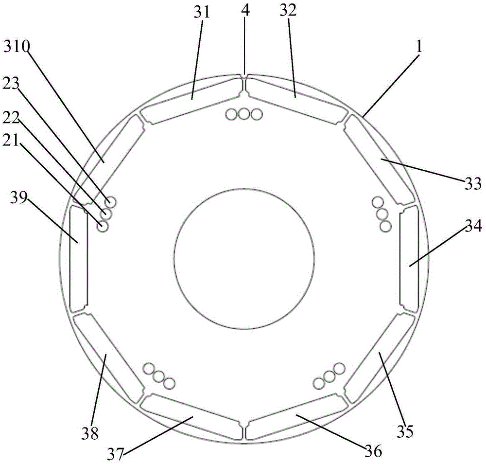
[0025] The rotor skew pole structure of the permanent magnet synchronous motor provided by the present invention is a multi-stage rotor skew pole structure formed by stacking a plurality of rotor punches 1 . The rotor punching 1 is made using a set of punching dies, so the design and shape of the rotor punching 1 are exactly the same.

[0026] Such as Figure 1-2 As shown, the rotor punch 1 has a ring structure, and the rotor punch 1 includes mounting holes 2 and magnet slots 3 . Such as figure 1 As shown, the magnet slots 3 are arranged in the rotor punch 1 at equal intervals adjacent to the ou...


PUM


Abstract

The invention relates to a rotor skewed pole structure for a permanent magnet synchronous motor. The rotor skewed pole structure is a multi-section rotor skewed pole structure formed by laminating a plurality of rotor punched sheets together, wherein each rotor punched sheet comprises installation holes and magnet grooves; the installation holes and the magnet grooves are respectively arranged in an area of the rotor punched sheet near the edge at equal intervals; the installation holes of the adjacent rotor punched sheets are staggered and aligned; and the magnet groove is used for installing a magnet. According to the rotor skewed pole structure for the permanent magnet synchronous motor disclosed by the invention, additional tools and moulds are unnecessary; only one set of punching mould is used; the specially-designed punched sheets are specially combined, such that the skewed pole can be realized; and the cogging torque is effectively reduced.

Description

technical field [0001] The invention relates to the field of permanent magnet synchronous motors and generators, in particular to a rotor oblique pole structure of permanent magnet synchronous motors. Background technique [0002] Permanent magnet synchronous motors are more and more used with higher operating efficiency to achieve energy saving effects. The permanent magnet in the permanent magnet synchronous motor will not change the strength of the magnetism according to the position and state of the motor, so the magnetic poles of the magnet will have different attractive forces on the stator teeth and slots in the process of running in the circumferential direction. It will cause the torque to fluctuate when the rotor rotates, and this fluctuation will cause the vibration and noise of the motor, especially for high-power motors, the vibration and noise caused by this reason are particularly obvious. That is, the cogging torque of the permanent magnet synchronous motor ...

Claims


Application Information

Patent Timeline
IPC IPC(8): H02K21/02H02K1/27H02K1/28
Inventor 王凯
Owner DIBAISHI MOTOR TECH SUZHOU CO LTD
Why Eureka
Try Eureka