
Motor

A technology of motors and rotors, applied in the field of motors, can solve problems such as difficult formation of magnetic circuits, and achieve the effect of reducing cogging torque

Inactive Publication Date: 2015-11-11
NIDEC SANKYO CORP
View PDF10 Cites 5 Cited by
  • Summary
  • Abstract
  • Description
  • Claims
  • Application Information

AI Technical Summary

Problems solved by technology

However, in this motor, since the auxiliary grooves are formed on the end faces of the salient poles, the facing area between the end faces of the salient poles and the permanent magnets is reduced by an amount equivalent to the auxiliary grooves, so it is difficult to make the lines of magnetic force flow on the end faces of the salient poles. effectively pass
That is, in this motor, it is difficult to form an effective magnetic circuit

Method used


Image

  • Motor
  • Motor
  • Motor

Examples


Embodiment Construction

[0035] Hereinafter, embodiments of the present invention will be described with reference to the drawings.

[0036] (The overall structure of the motor)

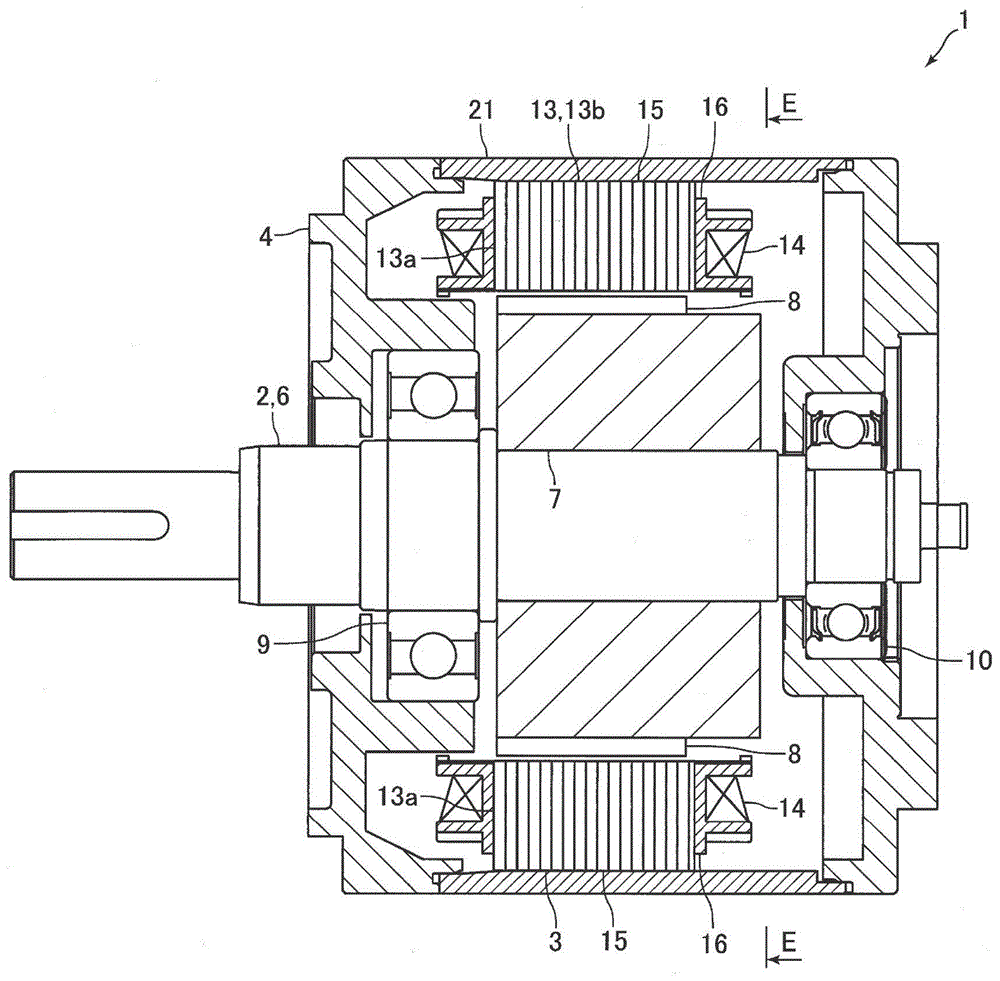
[0037] figure 1 It is a cross-sectional view of the motor 1 according to the embodiment of the present invention. figure 2 From figure 1 A diagram of the rotor 2 and the stator 3 shown in the E-E direction. image 3 Yes figure 2 A plan view of the permanent magnet 8 and the split core 15 shown.

[0038] The motor 1 of the present embodiment is an inner rotor type motor, and the outer diameter of the motor 1 is about 130 mm. Also, the capacity of the motor 1 is 850W to 2kW. like figure 1 As shown, the motor 1 includes a rotor 2 , a stator 3 arranged on the outer peripheral side (radial outer side) of the rotor 2 , and a motor case 4 . In the following description, the radial direction of the motor 1 (that is, the radial direction of the rotor 2 and the radial direction of the stator 3 ) is referred to as the “radial...


PUM


Abstract

The utility model discloses a motor. The number of bulged poles of a stator is twelve, and the number of magnetic poles formed on the peripheral surface of a rotor is ten. The motor not only can form an effective magnetic circuit, but also can reduce the cogging torque. In the motor, the stator (3) disposed at the radial peripheral side of the rotor (2) comprises a stator core (13) which is provided with twelve bulged poles (13a) bulging radially inwards. The rotor (2) comprises a plurality of permanent magnets (8) which are arranged in the peripheral direction in an adjacent manner, and are arranged opposite to tail end faces (13e) of the bulged poles (13a), wherein there are gaps between the permanent magnets (8) and the tail end faces (13e) of the bulged poles (13a). The number of the magnetic poles on the peripheral surface of the rotor (2) is ten. The tail end faces (13e) of the bulged poles (13a) form a concave curved surface through smooth connection surfaces, and surfaces (8b), opposite to the tail end faces (13e) of the bulged poles (13a), of the permanent magnets (8), form a convex curved surface. In the motor, the ratio R1 / R2 of the radius R1 of an imaginary circle contacting with a part of surfaces (8b) of the permanent magnets (8) to the curvature radius R2 of each of the surfaces (8b) of the permanent magnets (8) is from 0.4 to 0.55.

Description

technical field [0001] The present invention relates to a motor including a rotor and a stator arranged radially outside the rotor. Background technique [0002] Conventionally, a permanent magnet type motor including a rotor having permanent magnets and a stator disposed radially outside the rotor is known (for example, see Patent Document 1). In the motor described in Patent Document 1, the stator includes a stator core having nine salient poles protruding radially inward, and a driving coil, and the driving coil is wound around the salient poles. Furthermore, the rotor has a rotating shaft and six permanent magnets fixed to the outer peripheral surface of the rotating shaft. Six permanent magnets are fixed to the outer peripheral surface of the rotating shaft so as to be adjacent to each other in the circumferential direction of the rotor, and the number of magnetic poles formed on the outer peripheral surface of the rotor by the six permanent magnets is six poles. The ...

Claims


Application Information

Patent Timeline
IPC IPC(8): H02K21/14H02K1/27
Inventor 山本登子雄
Owner NIDEC SANKYO CORP
Learn More