A detection device, electronic equipment and information processing method
A detection device and light beam technology, which is applied in the electronic field, can solve problems such as single structure, achieve technical effects, and realize the effect of diversified designs
- Summary
- Abstract
- Description
- Claims
- Application Information
AI Technical Summary
Problems solved by technology
Method used
Image

Examples
Embodiment 1
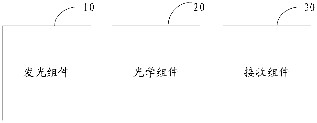
[0064] Please refer to figure 1 , is a functional block diagram of the detection device in the embodiment of the present application.
[0065] The detection device can be a separate optical detection device, such as fingerprint detection, or other detection devices with fingerprint detection functions, such as notebook computers, mobile phones, ID cards, etc. with fingerprint collection functions. Of course, other texture detections may also be used, such as texture detection of cultural relic devices. The detection device includes:
[0066] A light-emitting component 10, configured to emit an initial light beam;
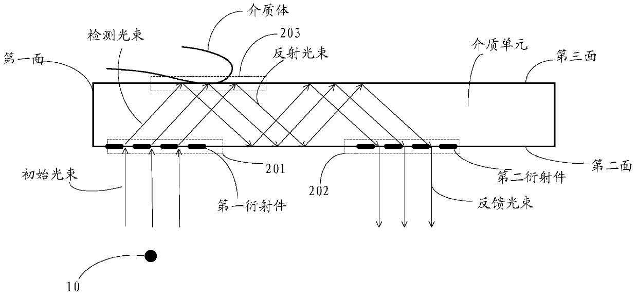
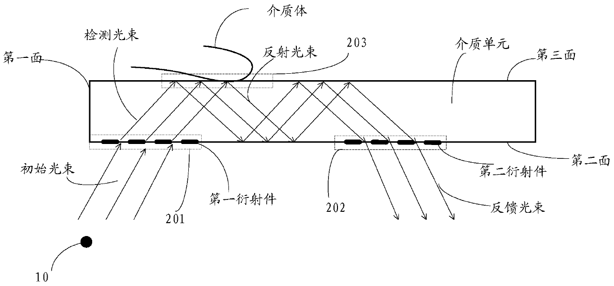
[0067] An optical component 20, wherein the optical component 20 is at least partly arranged in the irradiation area of the initial light beam, and at least part of the initial light beam is formed by the first region 201 of the first plane of the optical component incident on the optical component detection light beam; wherein, the optical assembly includes a ...
Embodiment 2
[0089] Please refer to Image 6 Based on the same inventive concept as the first embodiment of the present application, the second embodiment of the present application provides a functional block diagram of an electronic device, such as a notebook computer, a mobile phone, an ID card, a wearable device, etc. including an optical detection device. The electronic equipment includes:
[0090] The detection device 60, wherein the detection device 60 includes a light-emitting component for emitting an initial light beam; an optical component is at least partially arranged in the irradiation area of the initial light beam, and at least part of the initial light beam is emitted by the first light beam of the optical component The first area within a plane is incident on the optical assembly to form a detection beam; wherein, the optical assembly includes a beam for constraining the detection beam in the optical assembly, which is arranged in the irradiation area of the at least ...
Embodiment 3
[0110] Based on the same inventive concept as the first embodiment of the present application, please refer to Figure 8 , Embodiment 3 of the present application also provides an information processing method, including:
[0111] S801: The light-emitting component in the detection device emits an initial light beam;
[0112] S802: At least part of the initial light beam is incident on the first diffraction member in the optical component in the first area of the first plane of the optical component in the detection device to form a detection beam, wherein the optical component is at least partially configured In the irradiated area of the initial light beam, and the optical component includes a medium unit for confining the detection beam to propagate inside the optical component, the first diffractive element and the second diffractive element, the The first diffractive element is disposed in the first area, and the second diffractive element is disposed in a second are...
PUM
| Property | Measurement | Unit |
|---|---|---|
| refractive index | aaaaa | aaaaa |
Abstract
Description
Claims
Application Information
 - Generate Ideas
- Intellectual Property
- Life Sciences
- Materials
- Tech Scout
- Unparalleled Data Quality
- Higher Quality Content
- 60% Fewer Hallucinations
Browse by: Latest US Patents, China's latest patents, Technical Efficacy Thesaurus, Application Domain, Technology Topic, Popular Technical Reports.
© 2025 PatSnap. All rights reserved.Legal|Privacy policy|Modern Slavery Act Transparency Statement|Sitemap|About US| Contact US: help@patsnap.com