Backlight module

A backlight module and module technology, applied in the field of backlight modules, can solve problems such as the single structure of liquid crystal modules and the inability to overcome the Mura problem

Active Publication Date: 2014-12-10
TCL CHINA STAR OPTOELECTRONICS TECH CO LTD
View PDF5 Cites 0 Cited by
  • Summary
  • Abstract
  • Description
  • Claims
  • Application Information

AI Technical Summary

Problems solved by technology

[0004] In view of the deficiencies in the existing technology, the present invention provides a backlight module, which solves the insurmountable Mura problem caused by the single structure of the existing liquid crystal module, and reduces the influence of lamp shadows on the viewing effect

Method used


Image

  • Backlight module
  • Backlight module
  • Backlight module

Examples


Embodiment 1

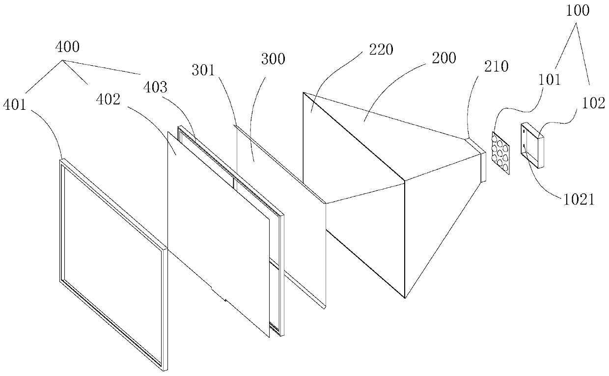
[0028] see figure 1 , is a schematic diagram of the exploded structure of the backlight module according to Embodiment 1 of the present invention. The backlight module includes a light source module 100 , a module light box 200 , a film set 300 and a display panel assembly 400 connected in sequence.

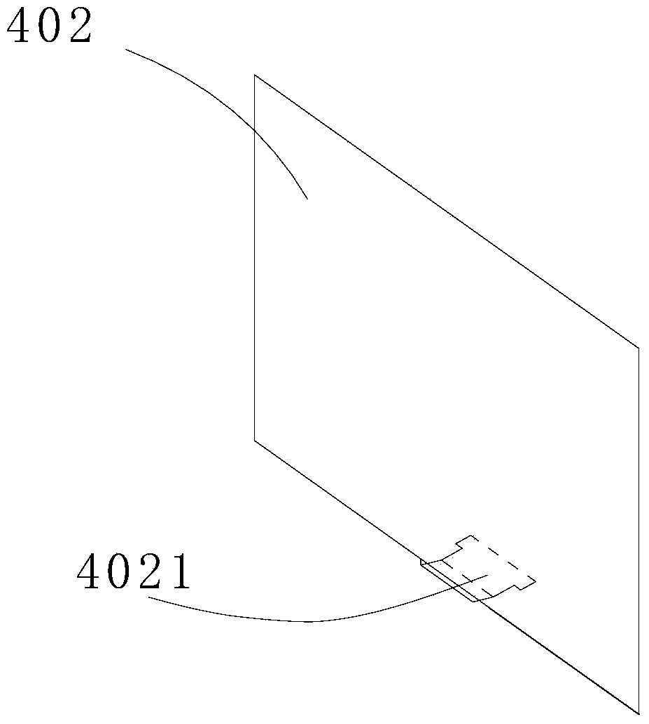
[0029] Wherein, the light source module 100 is used to emit light, and the module light box 200 is used to reflect the light emitted by the light source module 100. at the first open end 210 . The display panel assembly 400 is used to display images, and includes a module front frame 401, a display panel 402 and a plastic frame 403, which are arranged at the second opening end 220. The depth direction is movably disposed between the light source module 100 and the display panel assembly 400 .

[0030] Specifically, the inner surface of the modular light box 200 is coated with a reflective layer or pasted on the inner wall with a reflective film.

[0031] By setting the diaphra...

Embodiment 2

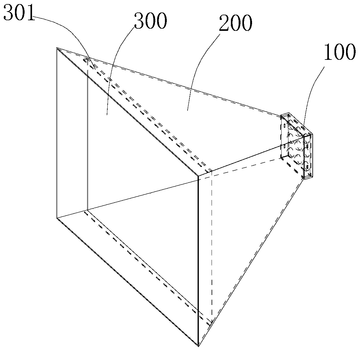
[0037] see Figure 4 , is a schematic exploded view of the structure of the backlight module according to Embodiment 2 of the present invention. Different from Embodiment 1, the second open end 220 of the module light box 200 is provided with a rectangular frame 201 , and the diaphragm group 300 elastically abuts against the rectangular frame 201 and is movable within the rectangular frame 201 .

[0038] In the modular light box 200, the frame part surrounded by trapezoidal panels is connected to the rectangular frame body 201, specifically, the opening of the frame body surrounded by trapezoidal panels extends outwards to form a stepped surface 610 connected to the rectangular frame body 201 , the stepped surface 610 corresponds to the second extreme position where the diaphragm set 300 moves.

[0039] In other embodiments, the frame body surrounded by trapezoidal panels and the rectangular frame body 201 are integrally formed, and the rectangular frame body 201 is stretched...


PUM


Abstract

The invention discloses a backlight module. The backlight module comprises a light source module used for emitting light rays, a module lamp box used for reflecting the light rays emitted by the light source module, a display panel assembly arranged at the second open end and used for displaying images, and a diaphragm set arranged in the module lamp box and movably arranged between the light source module and the display panel assembly in the depth direction of the module lamp box, wherein the two ends of the module lamp box are open, the second open end is larger than the first open end, and the light source module is arranged at the first open end. The diaphragm set is designed into the structure capable of moving in the depth direction of the module lamp box, the diversified design of the structure of the module lamp box is achieved, the problem of Mura generated when a liquid crystal module is seen from different angles is solved, and the influences of lamp shadows on the viewing effect are reduced.

Description

technical field [0001] The invention relates to the display field, in particular to a backlight module mainly used in liquid crystal display panels. Background technique [0002] Mura (light shadow and shadow) refers to the phenomenon of various traces caused by uneven brightness of the display. It is mainly due to the visual color difference caused by different frequency responses to the perceived light source, resulting in a certain angle. It may appear that the display effect is not good. [0003] The commonly used direct-type LCD modules on the market have a single structure. When the observer needs to keep watching at a certain angle but the Mura problem occurs at this angle, the general direct-type light box structure cannot meet the needs of use, and there are certain limitations. Contents of the invention [0004] In view of the deficiencies in the prior art, the present invention provides a backlight module, which solves the insurmountable Mura problem caused by ...

Claims


Application Information

Patent Timeline
Patent Type & Authority Applications(China)
IPC IPC(8): F21S8/00F21V19/00F21Y101/02
CPCF21S8/00F21V19/00
Inventor 萧宇均石秦珺
Owner TCL CHINA STAR OPTOELECTRONICS TECH CO LTD
Why Eureka
Try Eureka