
System and method for monitoring state of bolt

A bolt and status technology, applied in the field of electronic applications, can solve problems such as the inability to accurately monitor the bolt pre-tightening force, the inability to grasp the attenuation status of the bolt pre-tightening force, and potential safety hazards, and achieve the effect of real-time monitoring of attenuation changes

Inactive Publication Date: 2016-01-20
RAILWAY ENG RES INST CHINA ACADEMY OF RAILWAY SCI +1
View PDF7 Cites 22 Cited by
  • Summary
  • Abstract
  • Description
  • Claims
  • Application Information

AI Technical Summary

Problems solved by technology

[0005] The embodiment of the present invention provides a system and method for monitoring the state of bolts, so as to at least solve the technical problem of potential safety hazards caused by the inability to accurately monitor the pre-tightening force of the bolts, resulting in the inability to grasp the attenuation of the pre-tightening force of the bolts

Method used


Image

  • System and method for monitoring state of bolt
  • System and method for monitoring state of bolt
  • System and method for monitoring state of bolt

Examples


Embodiment 1

[0028] According to an embodiment of the present invention, a system embodiment of a system for monitoring the state of a bolt is provided. It should be noted that the steps shown in the flowchart of the accompanying drawings can be executed in a computer system such as a set of computer-executable instructions, Also, although a logical order is shown in the flowcharts, in some cases the steps shown or described may be performed in an order different from that shown or described herein.

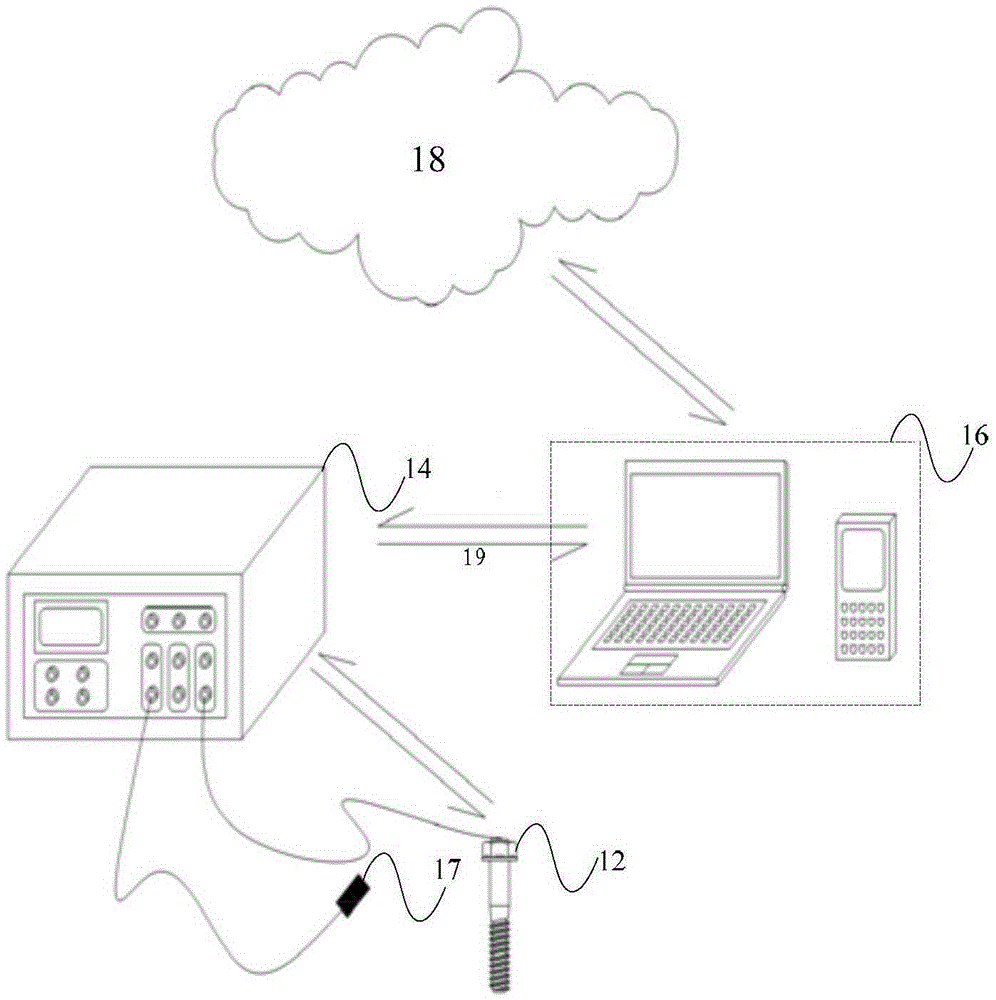
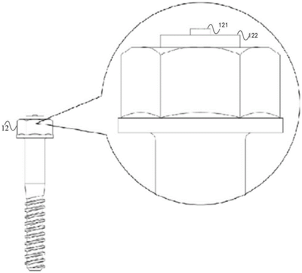
[0029] figure 1 is a schematic structural diagram of a system for monitoring the state of bolts according to an embodiment of the present invention, such as figure 1 As shown, the system includes: intelligent bolt 12, bolt pretension tester 14 and data processing terminal 16, wherein,

[0030] Smart bolt 12, used to generate bolt state parameters;

[0031] The bolt pretension tester 14 is connected with the smart bolt 12 through communication, and is used for collecting bolt state parameter...

Embodiment 2

[0069] According to an embodiment of the present invention, an embodiment of a method for monitoring the state of a bolt is provided. It should be noted that the steps shown in the flow chart of the accompanying drawings can be executed in a computer system such as a set of computer-executable instructions, and, Although a logical order is shown in the flowcharts, in some cases the steps shown or described may be performed in an order different from that shown or described herein.

[0070] Figure 4 is a schematic flow chart of a method for monitoring the state of a bolt according to an embodiment of the present invention, such as Figure 4 As shown, the method includes the following steps:

[0071] Step S402, collecting the bolt state parameters of the smart bolt through the bolt pretension tester;

[0072] Step S404, calculating the pretightening force of the smart bolt according to the bolt state parameters;

[0073] Step S406, comparing the pre-tightening force with the...


PUM


Abstract

The present invention discloses a system and method for monitoring the state of a bolt. The method comprises a step of collecting the bolt state parameter of an intelligent bolt through a bolt pretightening force tester, a step of calculating the pretightening force of the intelligent bolt according to the bolt state parameter, a step of comparing a prestored pretightening force measurement record and the pretightening force and determining whether the pretightening force of the intelligent bolt is in a preset safety range, and a step of uploading the pretightening force to a server when the judgment result is zero. According to the system and the method, the technical problem of hidden danger brought by the no control of the attenuation condition of the bolt pretightening force caused by the condition that the pretightening force of the bolt can be not accurately monitored is solved.

Description

technical field [0001] The invention relates to the technical field of electronic applications, in particular to a system and method for monitoring the state of bolts. Background technique [0002] Bolt pair is a common mechanical structure in mechanical applications. In specific application scenarios, taking railway structure assembly as an example, in various railway systems, most structures such as fastener systems, sound barrier systems or turnout areas are The assembly method of bolt pair is adopted. The assembly quality of the bolt pair interface mainly depends on the control of the bolt pre-tightening force. When the bolt does not reach the preset pre-tightening force when the bolt is tightened, the service life of the bolt pair will be reduced. At the same time, during the operation of the railway, if Insufficient monitoring of bolt pretightening force at key parts of key structures will lead to sudden failure of bolt pairs and affect driving safety. [0003] In th...

Claims


Application Information

Patent Timeline
Patent Type & Authority Applications(China)
IPC IPC(8): G01L5/24
Inventor 闫子权杜祖良杜青阳肖俊恒方杭玮
Owner RAILWAY ENG RES INST CHINA ACADEMY OF RAILWAY SCI
Learn More