
Electro-hydraulic driving system for sluice valve and sluice valve

A driving system and gate valve technology, applied in valve details, valve devices, engine components, etc., can solve the problems of oil cylinder or structure being damaged, accumulator filled with liquid, and unable to implement, so as to prevent water hammer phenomenon and facilitate system layout , the effect of compact structure

Active Publication Date: 2016-01-20
HUNAN SHANYUANAN AUTOMATIC CONTROL SYST
View PDF7 Cites 20 Cited by
  • Summary
  • Abstract
  • Description
  • Claims
  • Application Information

AI Technical Summary

Problems solved by technology

[0003] Patents CN202012516U and CN201110057860 "A Hydraulic Actuator for Coal Mine Automatic Drainage" have problems: 1. Although the emergency opening / closing power problem has been solved, it is impossible for the actuator to fill the accumulator at any position. The accumulator can be filled with liquid only after the oil cylinder is stretched or retracted, which greatly limits the function expansion of the mechanism. For example, when the gate valve is kept half-open, it cannot be implemented when the accumulator needs to be filled with liquid; 2. There is no system detection and alarm, fault self-diagnosis function, high reliability requirements for safety emergency equipment, and whether the charging pressure of the emergency accumulator meets the requirements cannot provide real-time dynamic detection and judgment; 3. According to the two principles it provides, the emergency function is in the electromagnet It is only effective when the power is on, and what is needed should be the emergency valve closing function in case of power failure; 4. The parallel bars are driven, which is prone to out-of-synchronization and leads to the problem of suffocation of the oil cylinder or structure, which is not practical in actual use.
[0005]Patent CN201110075968 "A Mining Submersible Electro-hydraulic Control Gate Valve" uses a bidirectional gear pump to drive the oil cylinder to open and close the gate valve. The control is simple, but there is no emergency function

Method used


Image

  • Electro-hydraulic driving system for sluice valve and sluice valve

Examples


Embodiment Construction

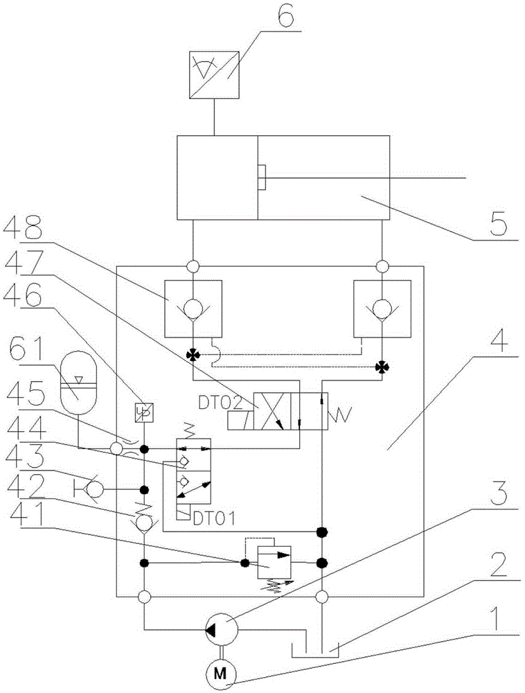
[0022] The present invention is described in detail below in conjunction with accompanying drawing, as figure 1 As shown, a gate valve electro-hydraulic drive system includes a motor 1, a hydraulic pump 3, an integrated control valve 4, an oil cylinder 5, an accumulator 61, a hydraulic oil tank and pipeline accessories 2, a monitoring and control system; an integrated control valve 4 Including overflow valve 41, one-way valve 42, quick connector 43, two-position three-way electromagnetic ball valve 44, throttle valve 45, pressure sensor 46, two-position four-way electromagnetic reversing valve 47, hydraulic control one-way valve 48, among which There are two hydraulically controlled one-way valves 48, one connected to the upper and lower chambers of the oil cylinder;

[0023] The hydraulic pump 3 is driven by the motor 1, its oil suction port is connected with the oil tank 2, the pressure oil port is connected in parallel to protect the overflow valve 4a, the oil return port ...


PUM


Abstract

The invention discloses an electro-hydraulic driving system for a sluice valve and the sluice valve. The electro-hydraulic driving system for the sluice valve comprises a motor, a hydraulic pump, an integrated control valve, an oil cylinder, an energy accumulator, a hydraulic oil tank and a monitoring and control system. The integrated control valve comprises an overflow valve, a check valve, a quick connector, a two-position three-way electromagnetic ball valve, a throttle valve, a pressure sensor, a two-position four-way electromagnetic reversing valve and hydraulic control check valves. The electro-hydraulic driving system for the sluice valve and the sluice valve are mainly characterized in that an energy accumulator emergency function is achieved, and it is ensured that the work of the electro-hydraulic driving system is not influenced by liquid charging of the energy accumulator through the design of an oil circuit; meanwhile, the cushioned oil cylinder is applied so that a rear segment slow closing function of emergency valve closing can be achieved, and a water hammer phenomenon is effectively avoided. Meanwhile, a pressure measurement function is achieved so that on-line fault diagnosis and overload protection can be provided according to a pressure measurement result and an operation.

Description

technical field [0001] The invention belongs to the technical field of mine drainage, and in particular relates to an electro-hydraulic drive system for a gate valve and a gate valve. Background technique [0002] Due to its simple structure and good sealing performance, gate valves are widely used in water supply and drainage systems such as mines. The most common gate valve actuators on the market are handwheel switches. With the development of gate valves towards high pressure, large diameter and automation. Handwheel switch actuators can no longer meet the demand. At present, there is an electric execution scheme, which replaces the handwheel mechanism through the rotation of the motor and the torque increase of the reducer. On the one hand, it can reduce labor intensity, and on the other hand, it is easy to realize remote control; but there are many problems: mainly the load It is difficult to start, and overload protection is not easy to realize, which often causes ...

Claims


Application Information

Patent Timeline
IPC IPC(8): F16K31/04F16K31/122F16K37/00F16K47/02
CPCF16K31/04F16K31/1245F16K37/0041F16K47/023
Inventor 张银辉
Owner HUNAN SHANYUANAN AUTOMATIC CONTROL SYST
Learn More